PhotoRobot CASE 850 Panduan Pengguna
Panduan pengguna dan instalasi ini menyediakan instruksi teknis untuk perakitan, koneksi, dan penggunaan PhotoRobot CASE 850. Informasi ini bertujuan untuk mendukung pelanggan dalam pengaturan awal, pemahaman, dan pengoperasian robot oleh pelanggan.
Penting: Pemasangan awal sistem PhotoRobot harus selalu dilakukan oleh otoritas PhotoRobot yang berwenang. Otoritas dengan otorisasi untuk menginstal PhotoRobot adalah distributor yang disetujui, atau perwakilan dari pabrikan itu sendiri.
Catatan: Selalu merujuk ke Informasi & Instruksi Keselamatan PhotoRobot sebelum melakukan instalasi mandiri, penggunaan pertama, penyimpanan, atau servis perangkat PhotoRobot.
1. Tentang CASE 850
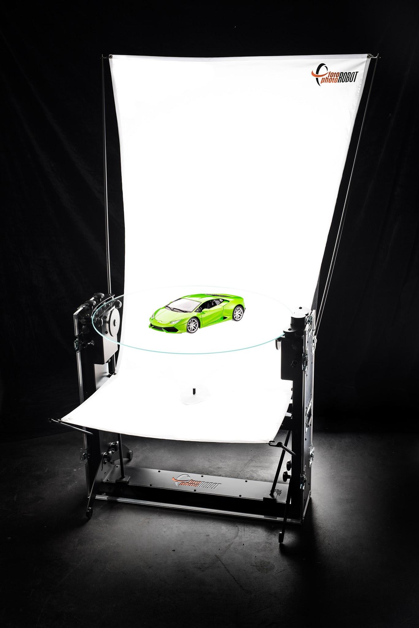
PhotoRobot CASE bertujuan untuk menetapkan standar baru dalam fotografi produk 360°. Ini menggabungkan mobilitas, daya tahan, presisi, dan kecepatan. Ini dapat digunakan di studio atau di lokasi. Konstruksinya yang unik memungkinkan Anda untuk mengambil foto produk yang disesuaikan dengan baik serta menangani produksi massal gambar 360 derajat.
Jelajahi keunggulan CASE 850 melalui panduan pengguna komprehensif ini, dimulai dengan 10 fitur utama yang akan mendefinisikan ulang alur kerja fotografi otomatis Anda.
- Seluruh robot CASE 850 muat dalam tas yang mudah dilipat & dibawa.
- Perakitan hanya membutuhkan waktu beberapa menit — sekitar 15.
- CASE cepat – ia berputar penuh dalam waktu sekitar 2,1 detik.
- Operasikan CASE dari komputer dengan aplikasi PhotoRobot Controls.
- Satu aplikasi mengontrol robot, kamera, dan lampu kilat secara bersamaan.
- Laser silang terintegrasi memastikan penempatan produk yang presisi.
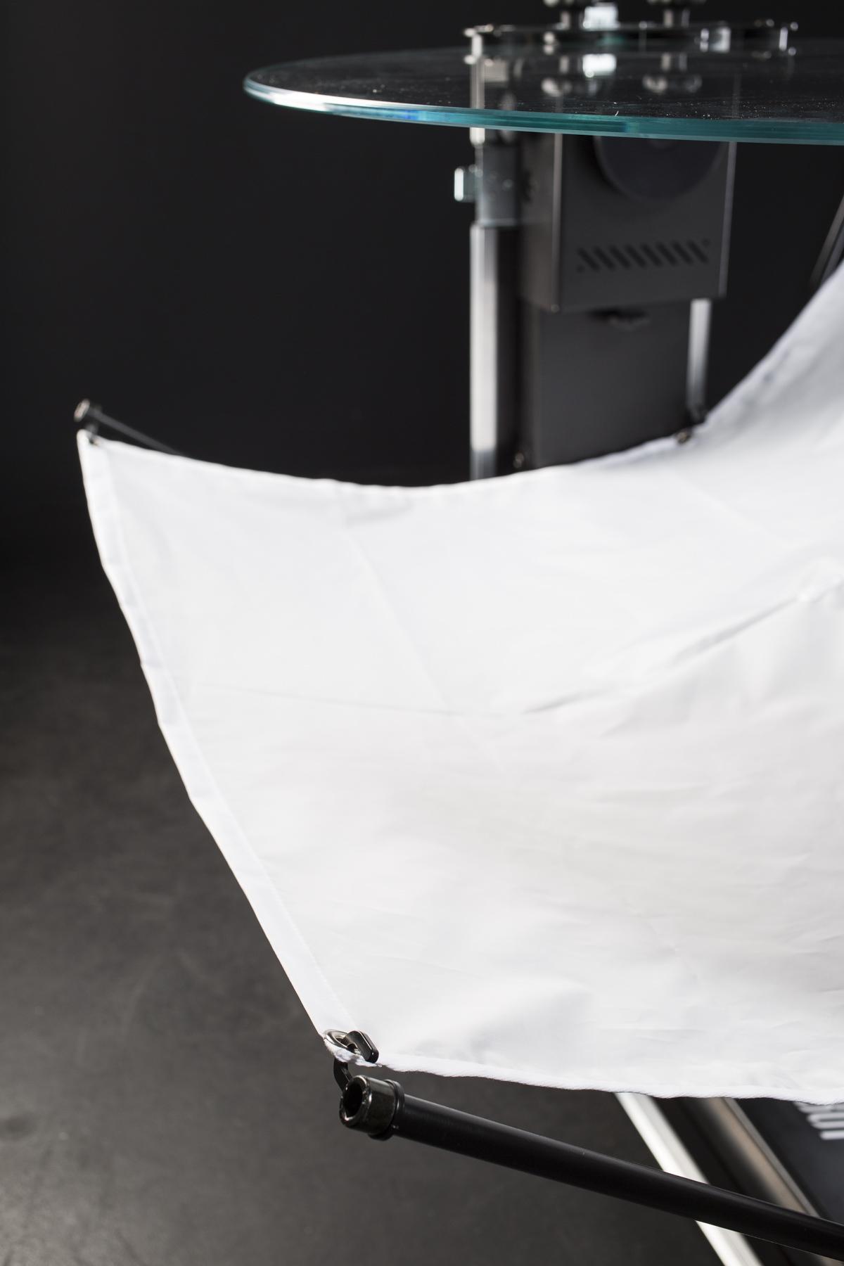
- Pelat kaca 850 mm sangat cocok untuk fotografi latar belakang putih murni.
- Enkodernya menjamin akurasi rotasi pelat puncak.
- Kaki yang dapat dilipat memberikan stabilitas tertinggi pada CASE 850.
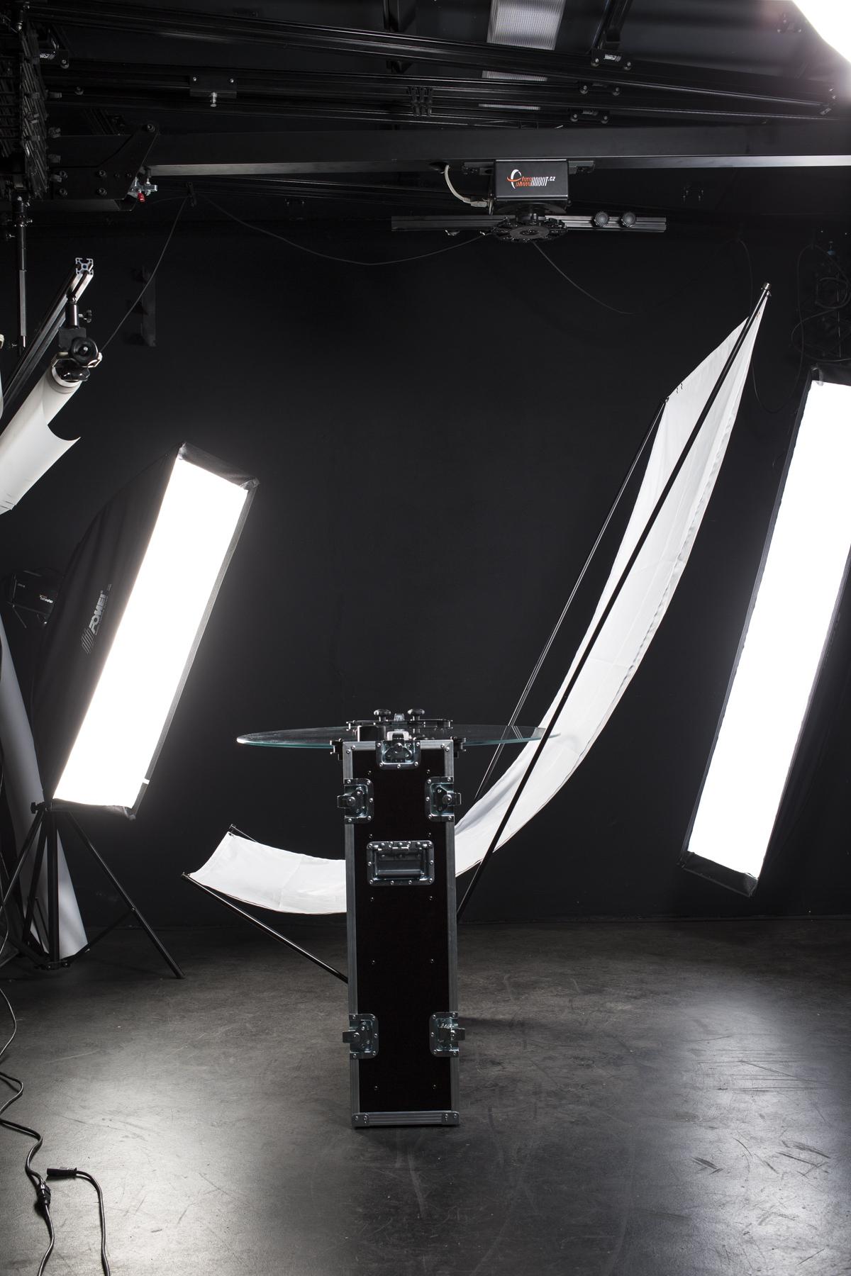
- Konstruksi yang lapang memberikan kebebasan untuk pencahayaan – cahaya dari bawah, atas, depan, belakang, atau samping.
1.1. Membongkar
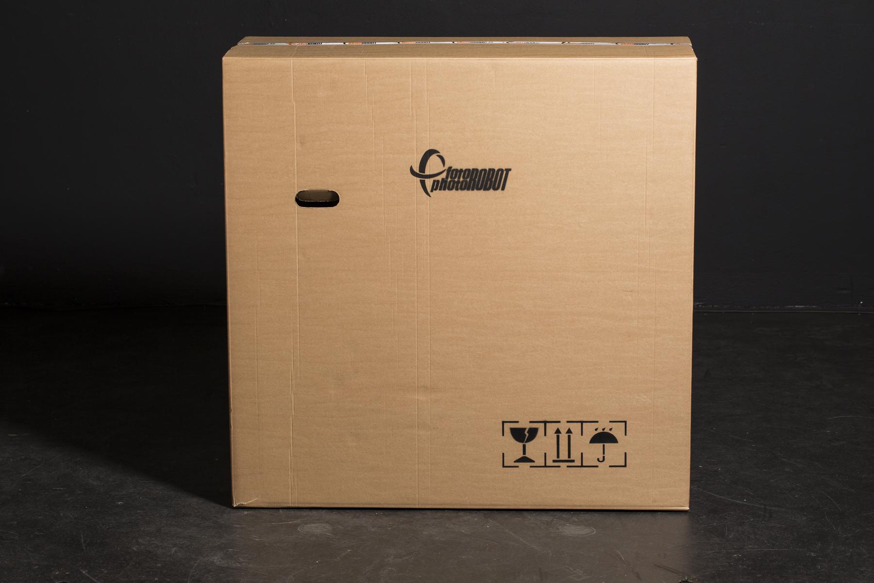
Meskipun CASE sangat tahan lama dan siap diangkut sebagai wadah itu sendiri, Anda mungkin ingin menyimpan kotak kardus asli yang kami gunakan untuk pengiriman. Mengingat semua mekanisme halus di dalam CASE, kotak kardus mungkin berguna untuk kondisi transportasi yang mungkin kasar. Untuk dapat menggunakan kembali kotak kardus dan tetap mudah membongkar CASE, harap gunakan petunjuk berikut.
- Letakkan kotak di permukaan yang bersih dan rata.
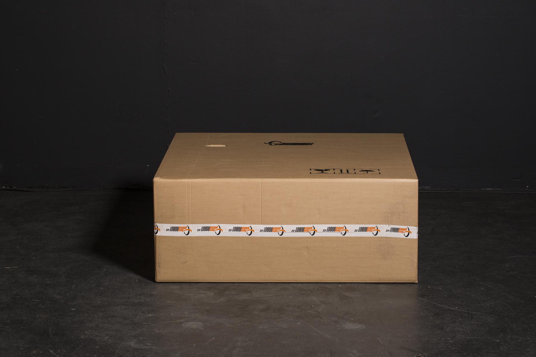
- Letakkan kotak di samping.
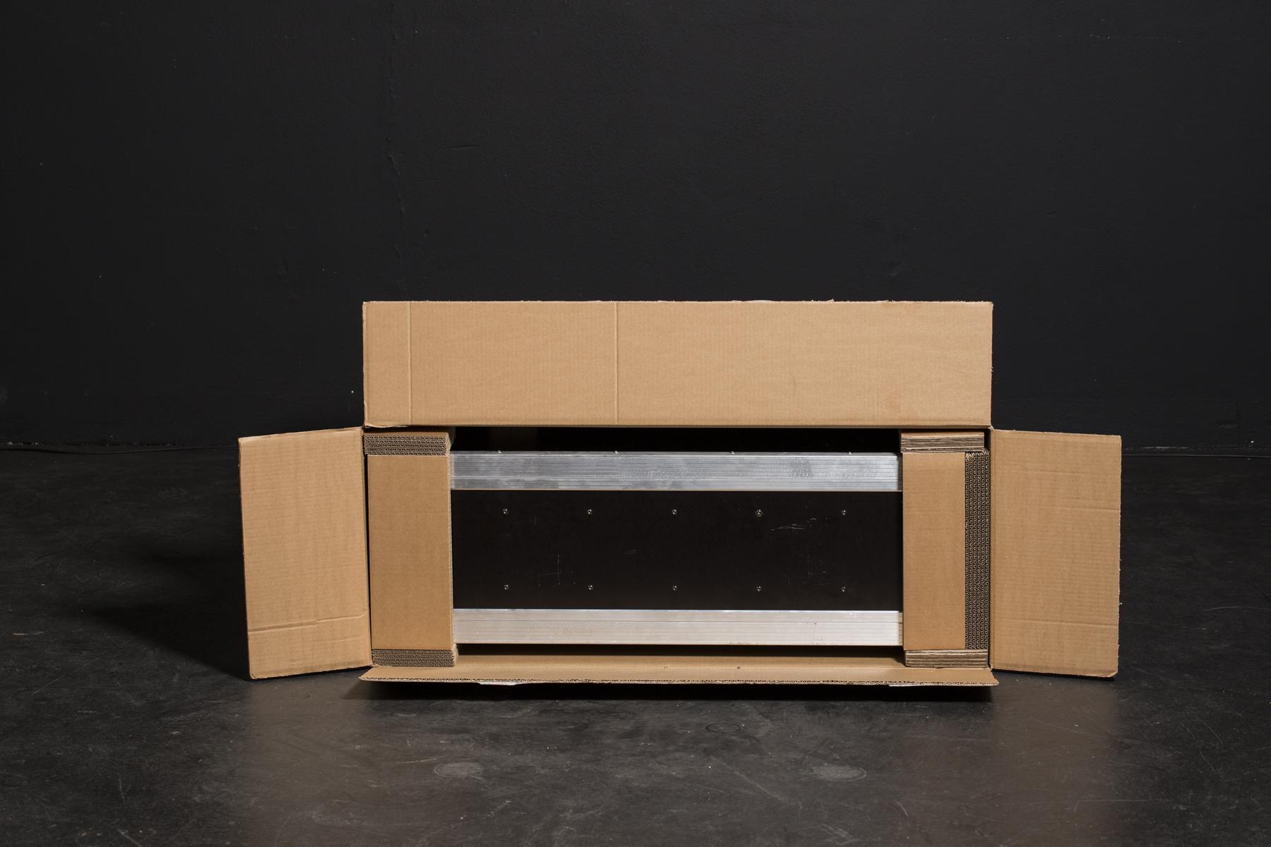
- Potong sisi terpendek.
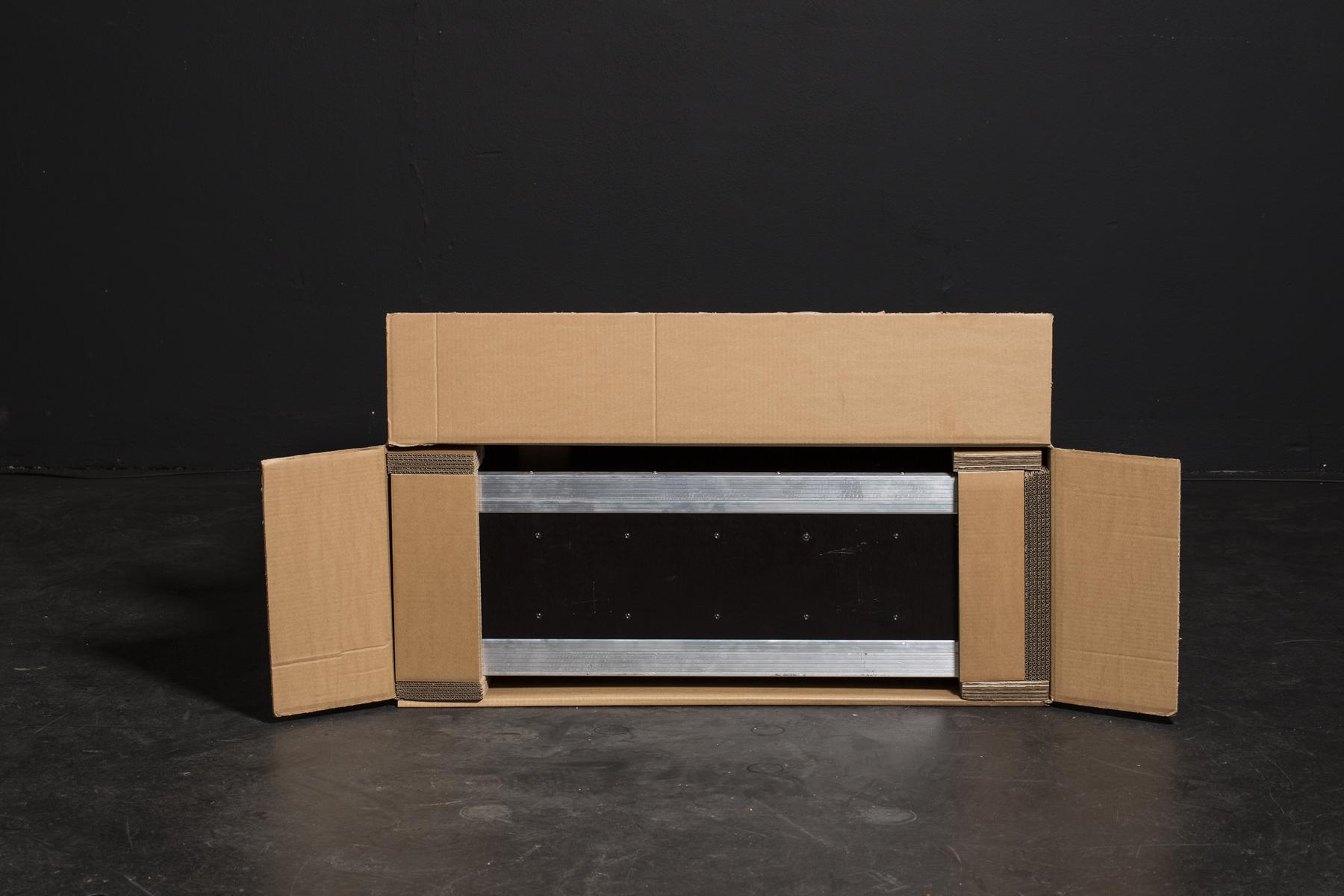
- Geser penutup panjang di bawah kotak.
- Berdirikan kotak pada sisi yang terbuka, dan tarik kardus dari CASE.
1.2. Pengepakan
Untuk membuat CASE sekecil dan seaman mungkin untuk diangkut, kami harus dengan cermat menentukan tempat yang tepat untuk setiap komponen agar terpasang dengan kuat. Petunjuk foto berikut akan memandu Anda melipat robot yang telah dirakit menjadi satu CASE.
Untuk mengembalikan CASE ke kotak kardus pengiriman, cukup balikkan langkah-langkah bab 1.1 - Pembongkaran.
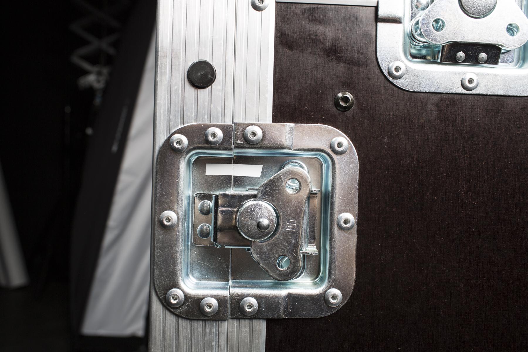
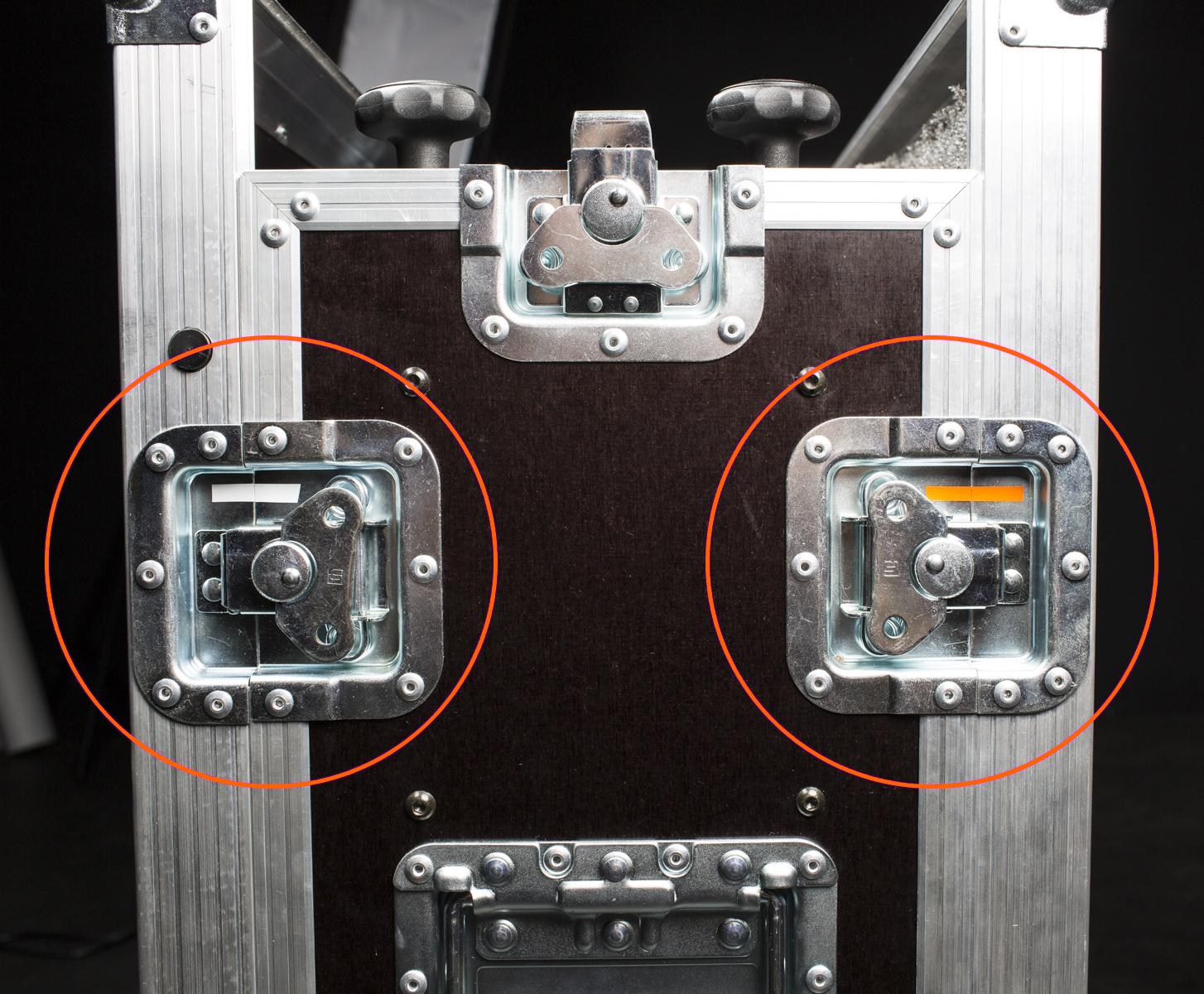
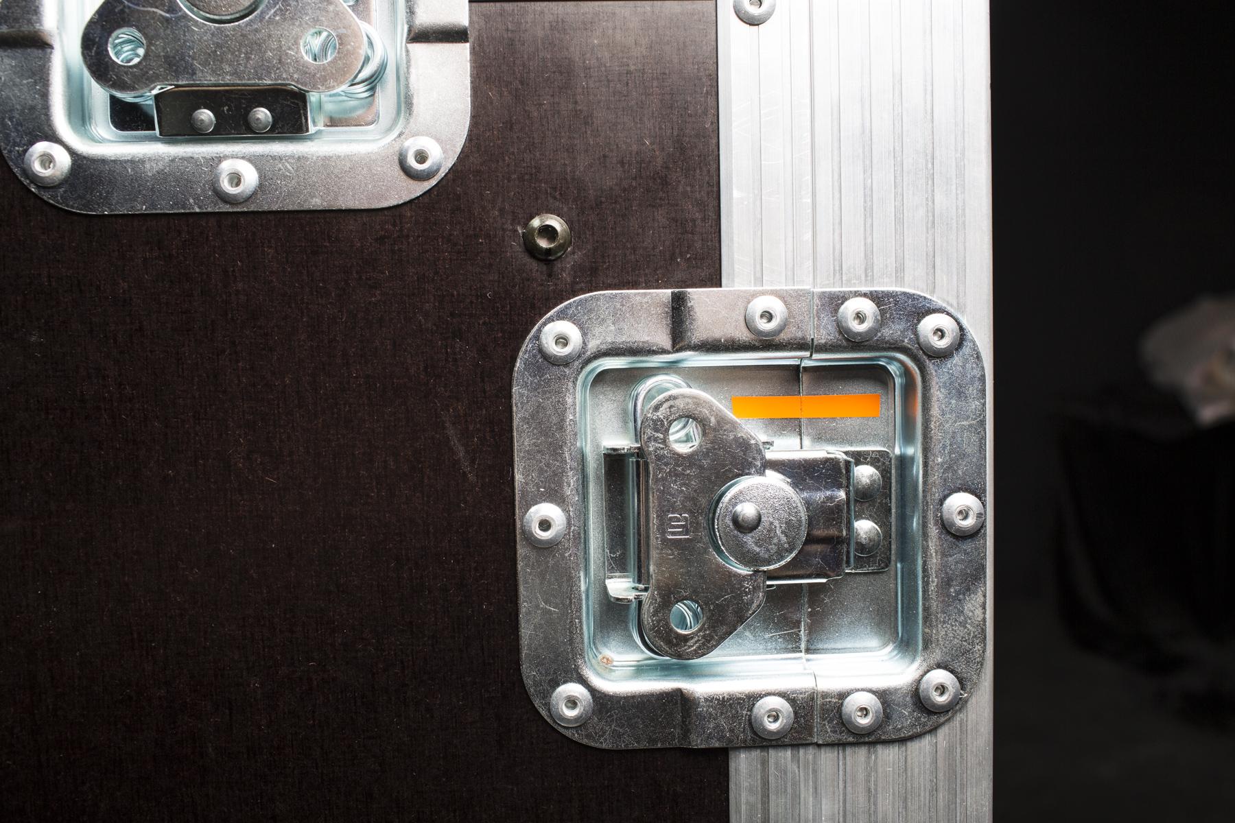
- Ingatlah, penting untuk merakit sisi-sisi sesuai dengan tata letak CASE bagian dalam. Untuk tujuan ini, ada tanda warna yang berbeda pada tutup pengunci (tergambar di atas).
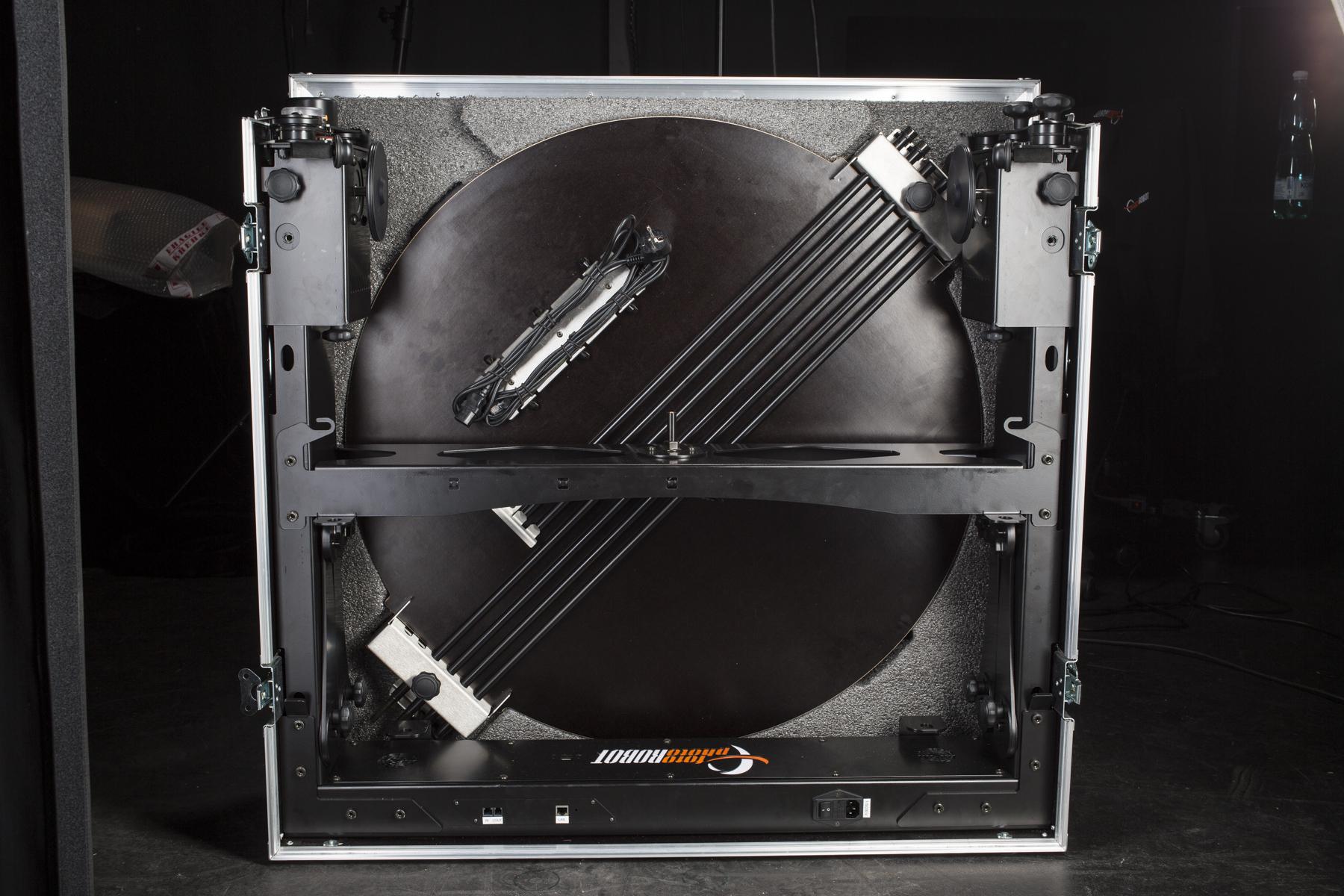
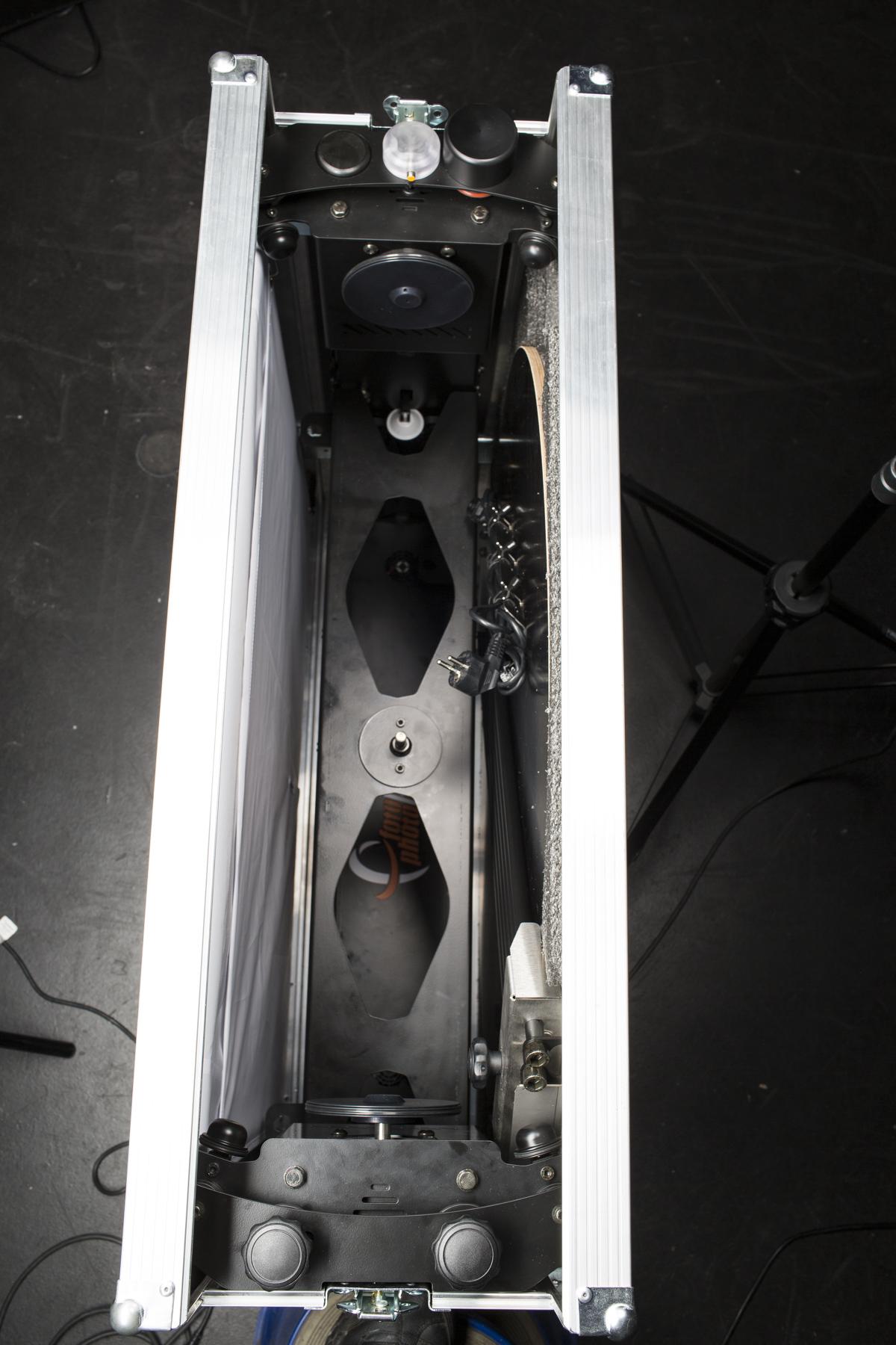
- Setelah berhasil dibongkar, CASE akan terlihat seperti pada dua gambar di atas.
- Ada area potongan di satu sisi casing untuk memasang konstruksi dudukan kaca.
- Hindari ketidakcocokan sisi-sisi untuk memastikan pas dengan tata letak bagian dalam.
- Kabel-kabel ditahan pada posisinya oleh karet gelang.
1.2.1. Lipat latar belakang ke sisi casing
- Ada metode canggih untuk melipat latar belakang ke sisi CASE untuk menghindari kerutan.
- Petunjuk langkah demi langkah ada di bawah.

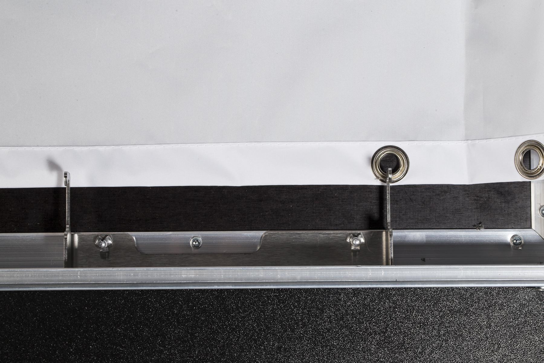
- Ambil bagian yang lebih lebar dari latar belakang miring dan pasang lubang ketiga ke sisi kanan dan kiri menggunakan kait luar. Tepi latar belakang masuk di bawah kait dalam.

- Lipat sudut-sudut latar belakang, lalu kaitkan lubang-lubang tersebut ke pengait.

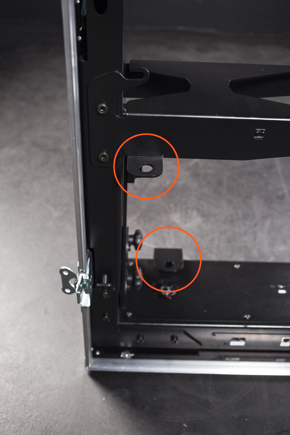
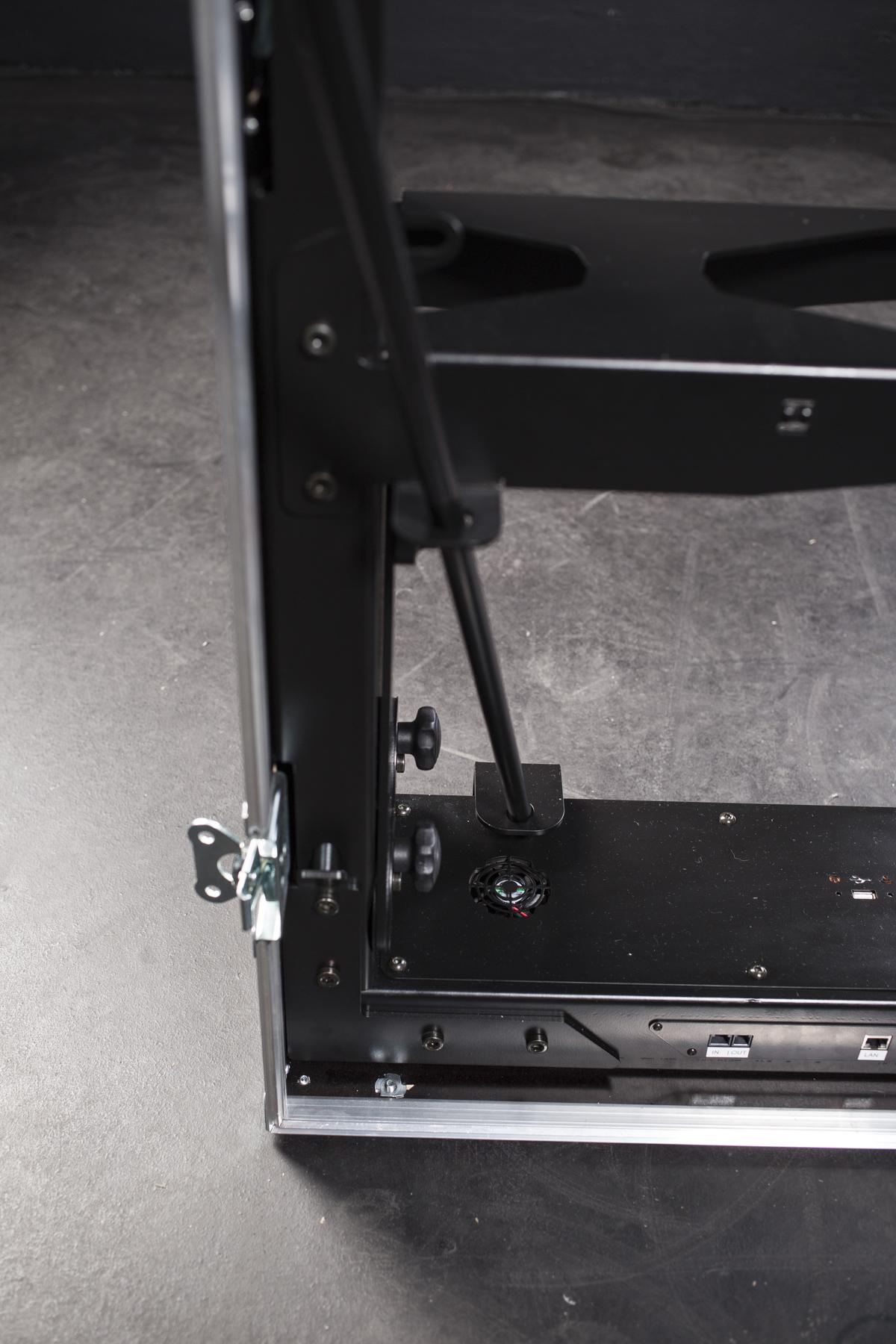
- Di sisi lain, kencangkan tiang di atas latar belakang.
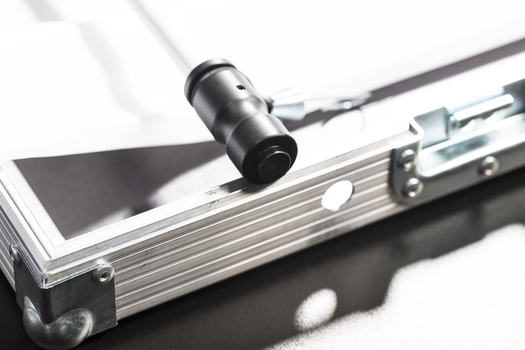
- Untuk mengencangkan tiang, tekan mekanisme pegasnya dan pasang ujung tiang ke dalam lubang jangkar.
- Lipat latar belakang di atas tiang pertama, lalu kencangkan tiang kedua ke sisi lainnya.

- Amankan lubang sudut latar belakang dengan kait pada karet gelang yang terpasang pada tiang.
1.2.2. Pasang pelat kaca dan tiang latar belakang ke sisi CASE
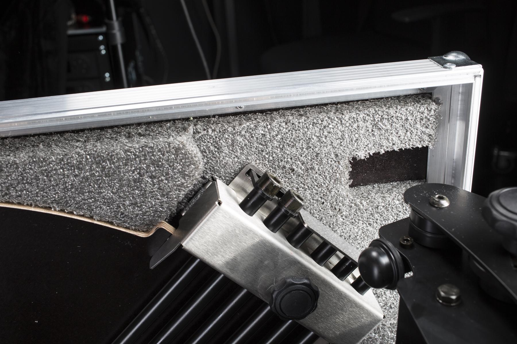
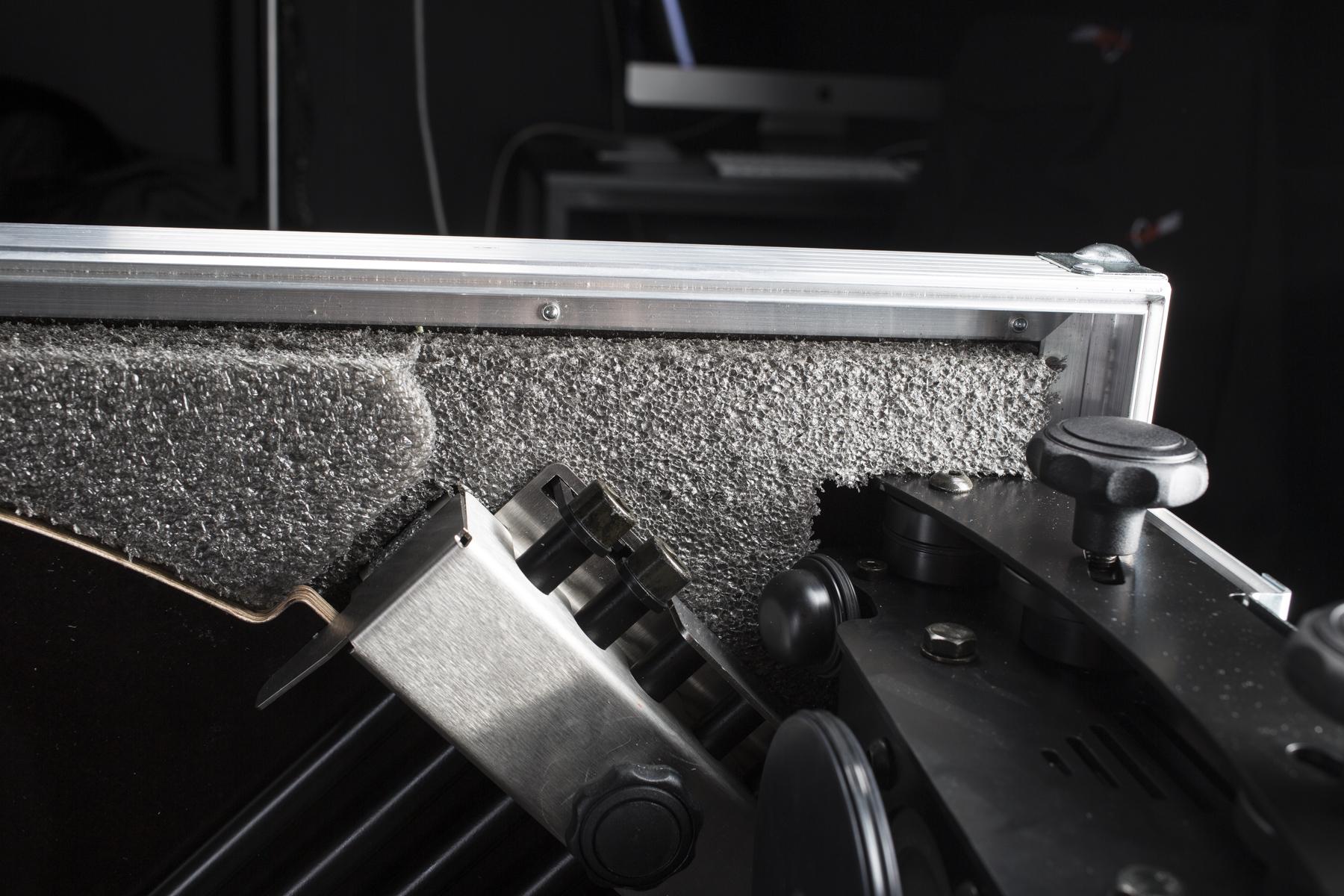
- Pastikan sisi bersih dan bebas dari halangan apa pun untuk menghindari kerusakan pada pelat kaca.
- Tempatkan pelat kaca ke area berongga di samping.
- Tutup pelat kaca dengan cakram pelindung kayu dengan tepi miring menghadap penahan latar belakang.
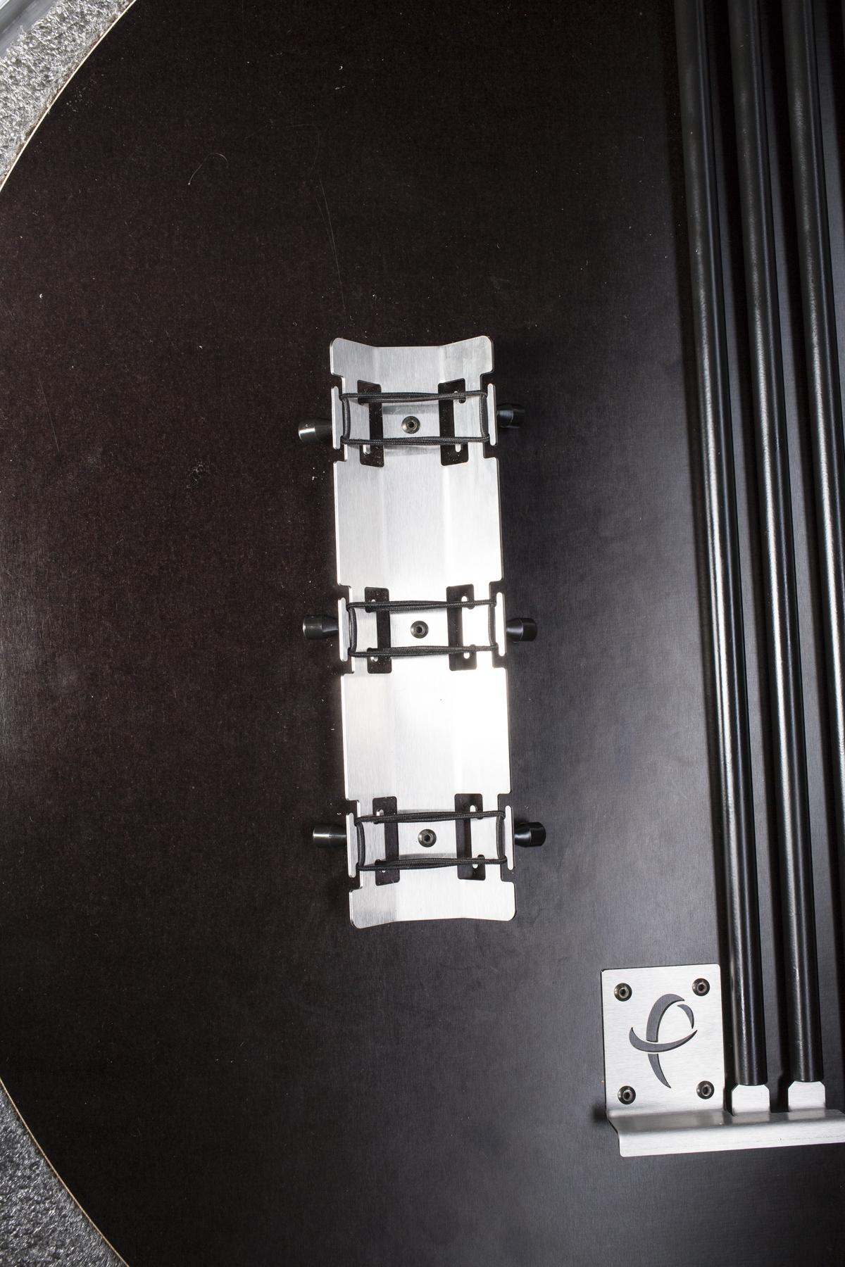
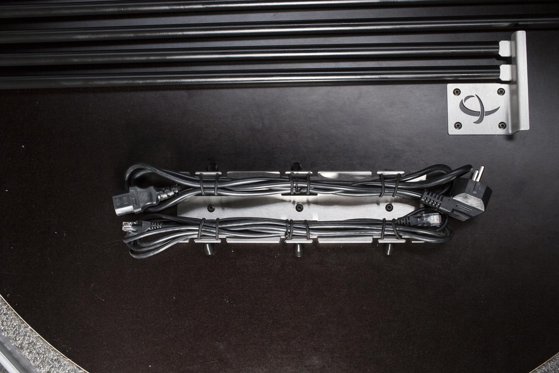
- Lepaskan karet gelang pada penahan kabel.
- Letakkan kabel-kabel ke dudukan.
- Kencangkan kabel dengan karet gelang.
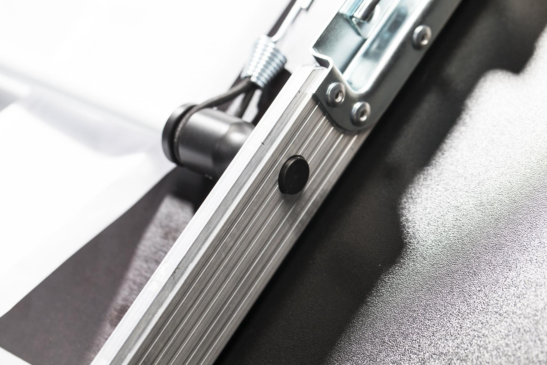
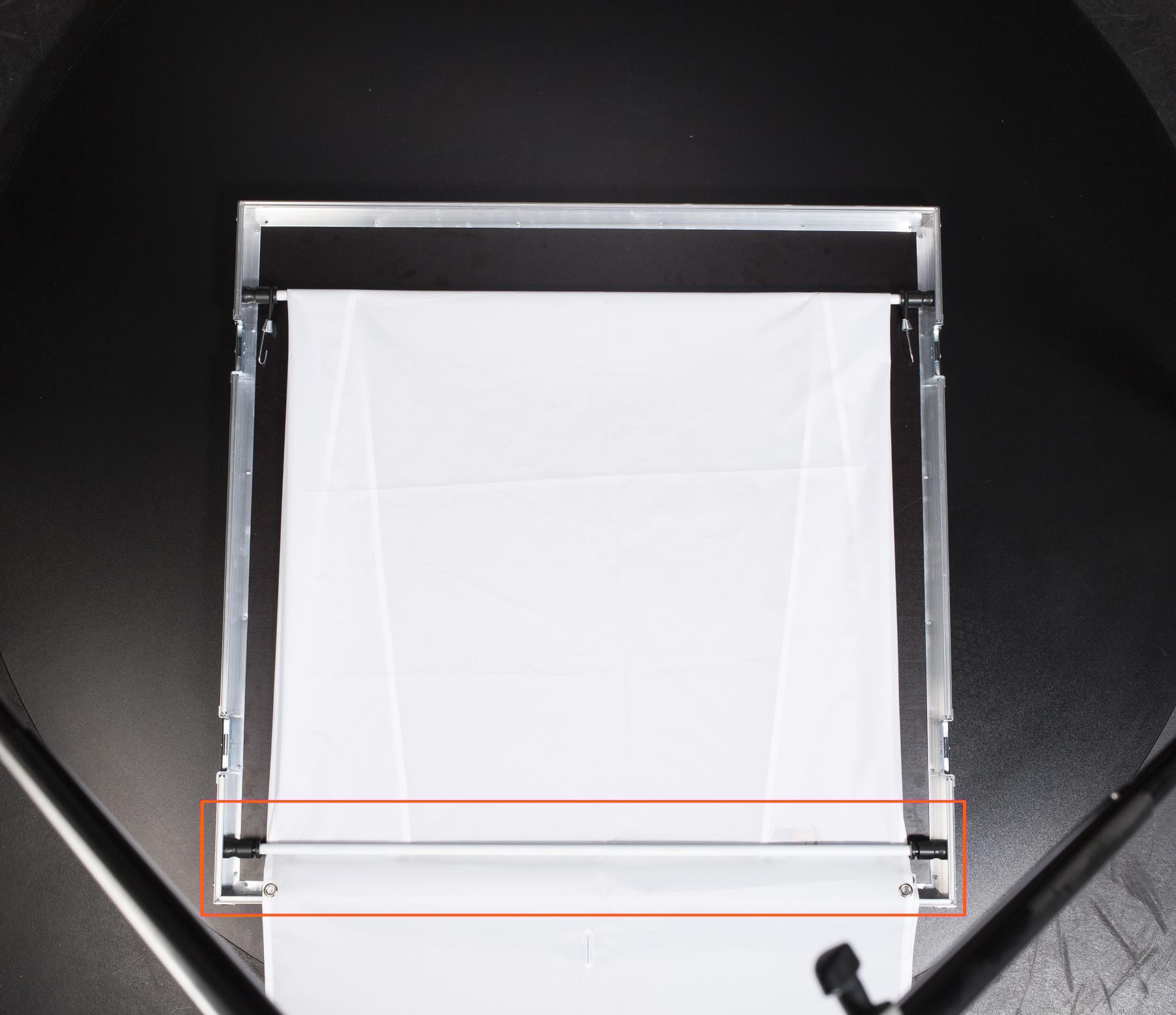
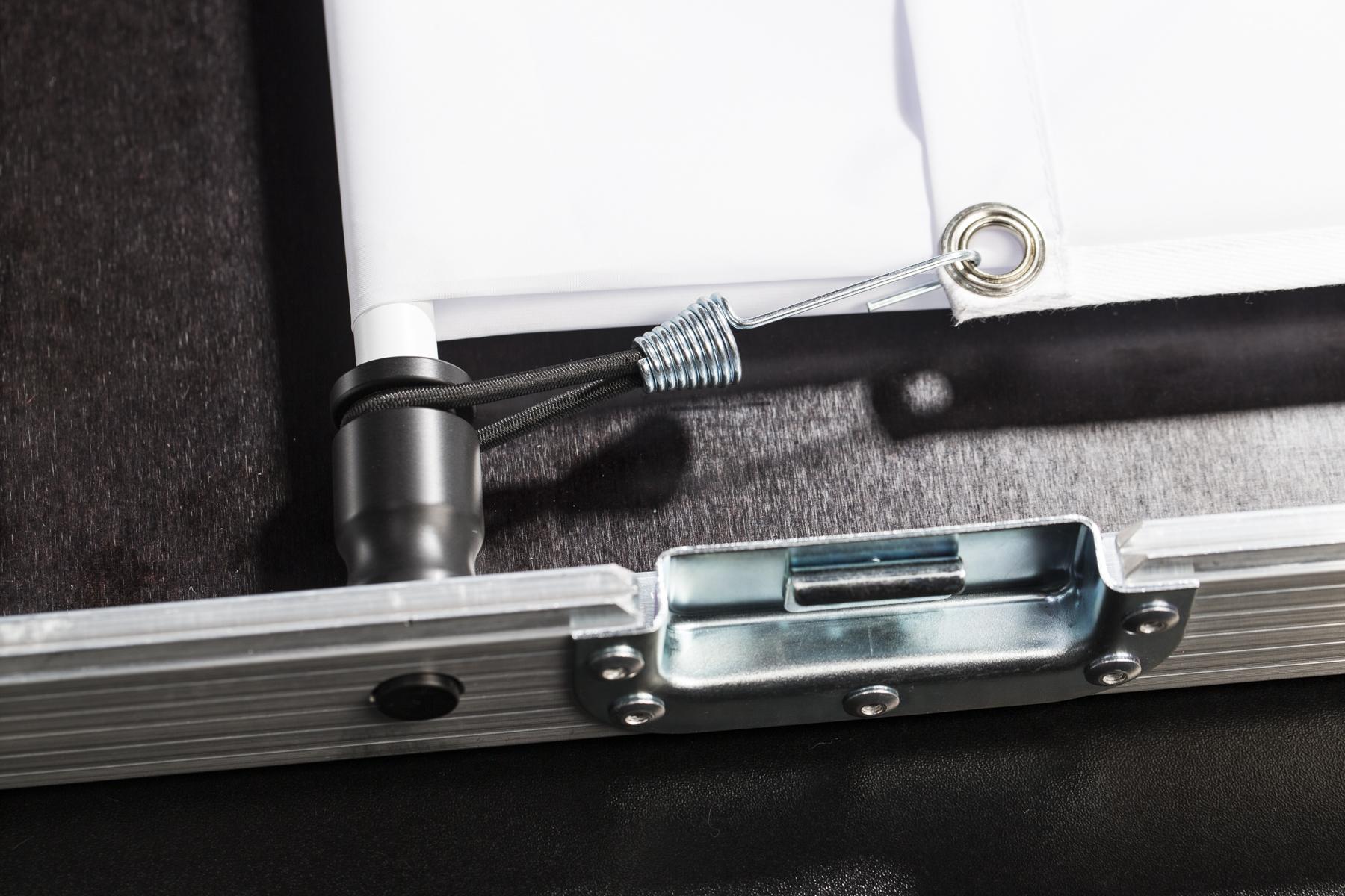
- Pasang penahan latar belakang ke samping.
- Kencangkan penahan latar belakang menggunakan klem.

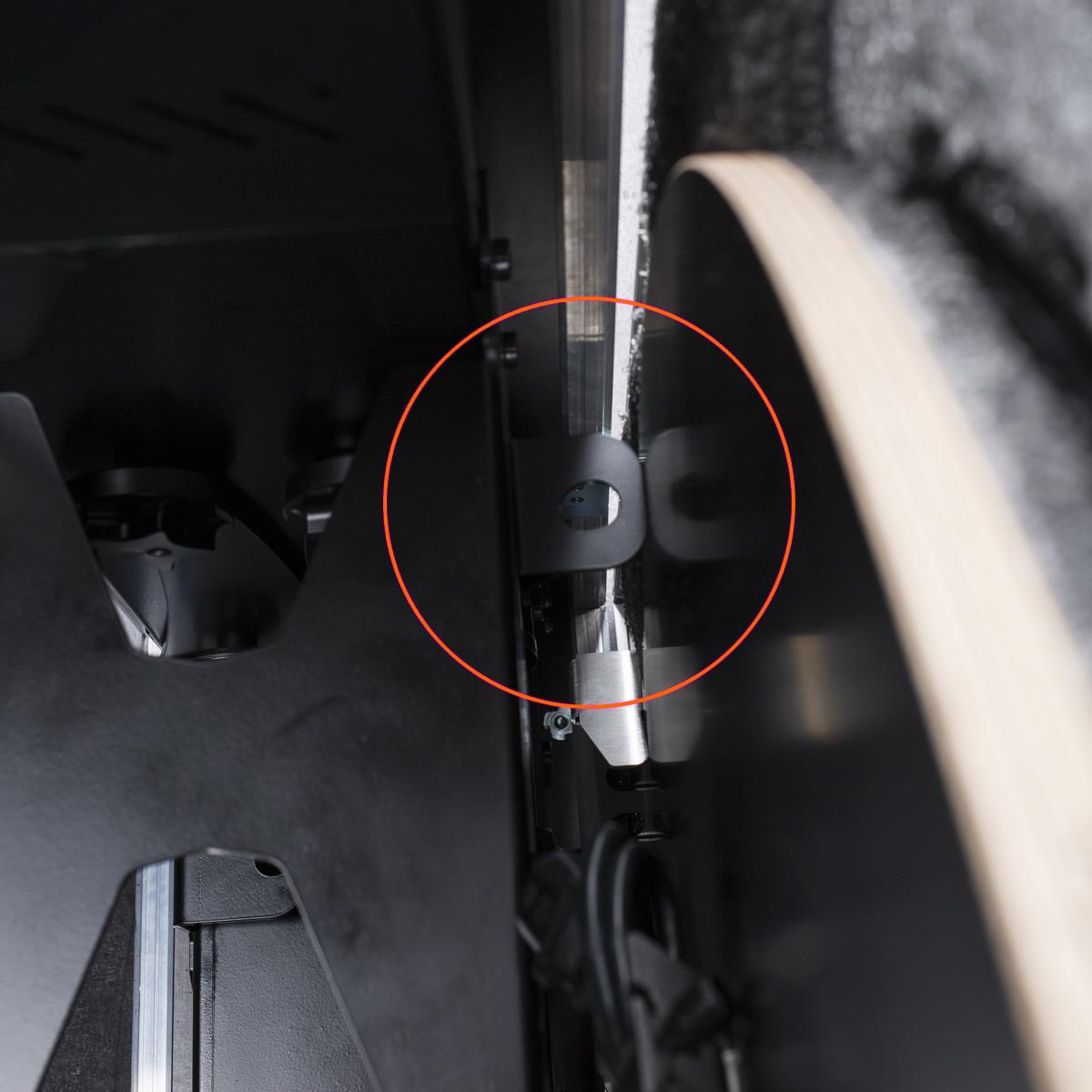
- Perhatikan bahwa ketika kait atas menghadap ke arah yang berlawanan, bilah latar belakang tidak ditempatkan dengan benar dan berisiko bergeser selama transportasi.

- Batang latar belakang ditempatkan dengan benar ketika kait atas saling berhadapan.
- Untuk menyatukan dasar mesin, sisi, dan bagian atas, kencangkan semua tutup pengunci.
1.3. Transportasi
Casing luar PhotoRobot CASE terbuat dari bahan yang sangat kokoh untuk membuat robot mudah dan aman untuk diangkut. Meskipun demikian, Anda harus menghindari benturan, tabrakan, atau guncangan yang dapat merusak elektronik.
Meskipun CASE hanya berbobot 62 kilogram (137 pon), tidak disarankan untuk membawanya sendiri; kami menyarankan untuk meminta bantuan asisten.
Kami merekomendasikan penggunaan kotak kardus asli untuk pengiriman. Untuk melakukannya, cukup balikkan langkah-langkah di bab 1.1 - Pembongkaran.
- Pegangan miring yang tahan lama berguna untuk memudahkan membawa CASE.
2. Isi Paket
PhotoRobot CASE dirancang untuk digunakan dengan berbagai cara dalam berbagai skenario dan lingkungan fotografi. Oleh karena itu, bersama dengan robot, kami menyediakan aksesori opsional untuk memenuhi semua kebutuhan spesifik yang mungkin dimiliki fotografer.
2.1. Robot CASE 850
CASE berisi perlengkapan dasar yang diperlukan untuk mengoperasikan robot, dan untuk memotret gambar STILL atau SPIN.
Apa yang termasuk dalam Case 850 Robot?
- Pelat kaca 850 mm (33,5 inci)
- Unit kontrol
- Latar belakang transparan dengan dudukan
- Laser silang untuk penentuan posisi produk yang presisi
- Kabel daya dan data
- Kaki yang dapat dilipat
- Encoder & probe kalibrasi
- Cincin-X cadangan
- Lug serbaguna untuk menahan lampu, pembagi cahaya, panel difusi, dll.
- Pegangan untuk transportasi yang nyaman
CATATAN: CASE tidak berisi kamera maupun lampu kilat.
2.2. Aksesori Opsional
Dengan bantuan aksesori opsional kami — disediakan secara terpisah, dengan biaya tambahan — Anda dapat menyederhanakan alur kerja Anda untuk memenuhi kebutuhan Anda. Silakan lihat detail lebih lanjut di bawah ini.
2.2.1. Modul Wi-Fi
Kami menyediakan modul Wi-Fi USB untuk memungkinkan Anda menghubungkan CASE ke jaringan nirkabel yang ada atau untuk membangun jaringan Wi-Fi Anda sendiri secara independen dari konektivitas jaringan lainnya. Untuk bekerja dengan PhotoRobot CASE, kami menjual dan merekomendasikan TP-LINK TL-WN721N yang telah diuji secara ekstensif (lihat spesifikasi teknisnya). Modul Wi-Fi tersedia dalam stok dan merupakan pilihan yang tepat untuk pekerjaan di lokasi di mana koneksi LAN tidak tersedia. Kapan pun koneksi kabel memungkinkan, kami merekomendasikan penggunaan LAN sebagai gantinya — ini lebih andal dan bebas dari interferensi nirkabel.
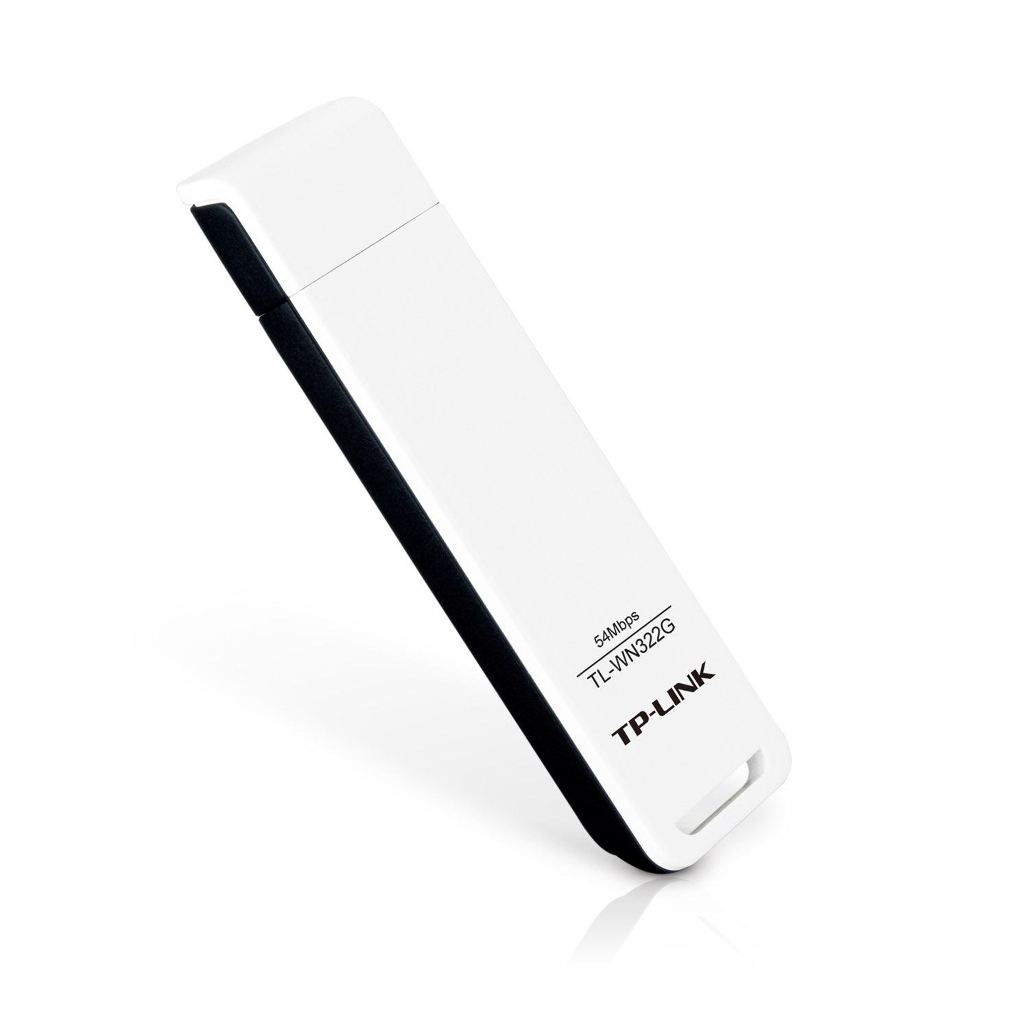
- Modul Wi-Fi menggunakan USB untuk terhubung ke CASE.
2.2.2. Pemicu Nirkabel
Sinkronisasi rana kamera dan pemberhentian urutan dapat dikontrol oleh pemicu nirkabel yang dicolokkan ke CASE. Kami berhasil menguji hähnel Combi TF Remote Control dengan kamera Canon.
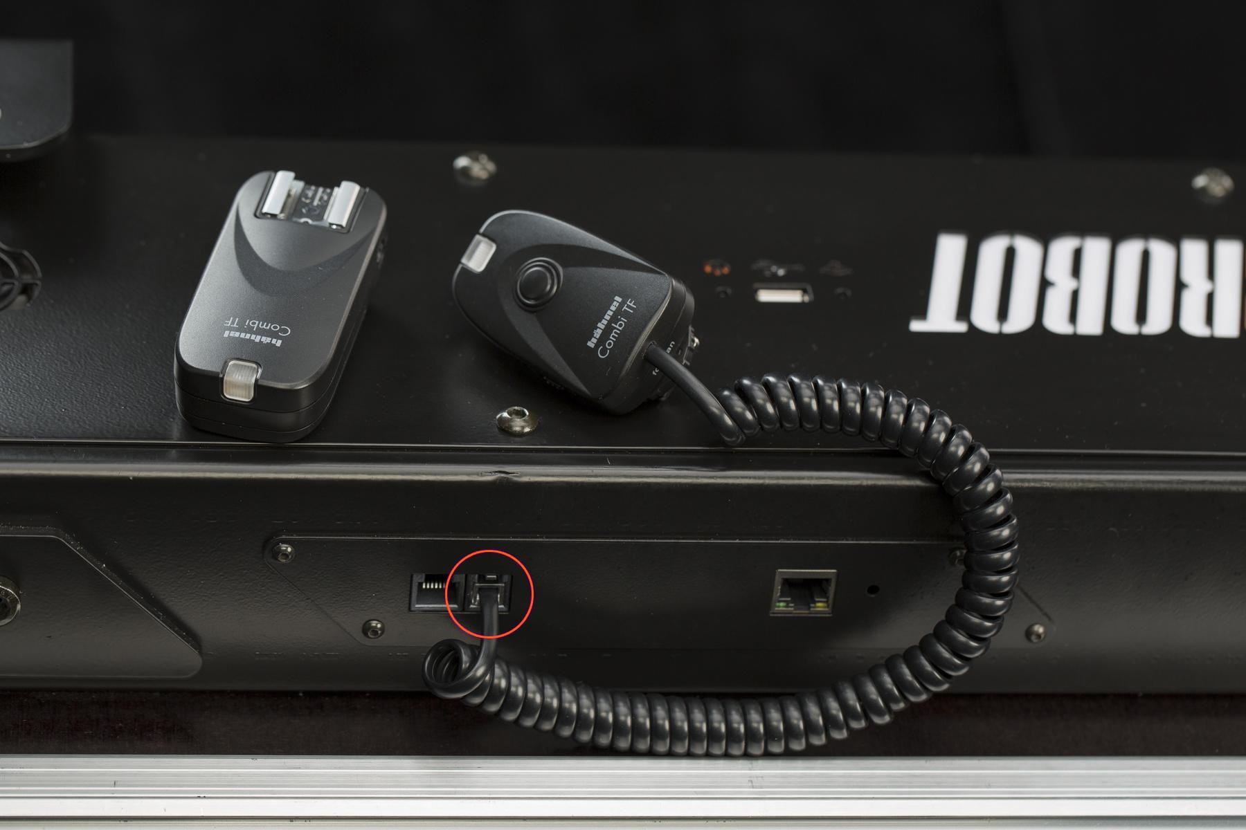
- Pemicu nirkabel menggunakan soket output 4P4C (RJ9) terintegrasi.
2.2.3. Pemicu Kabel
Sinkronisasi rana kamera dan penghentian urutan dapat dikontrol dengan mencolokkan pemicu kabel ke CASE.
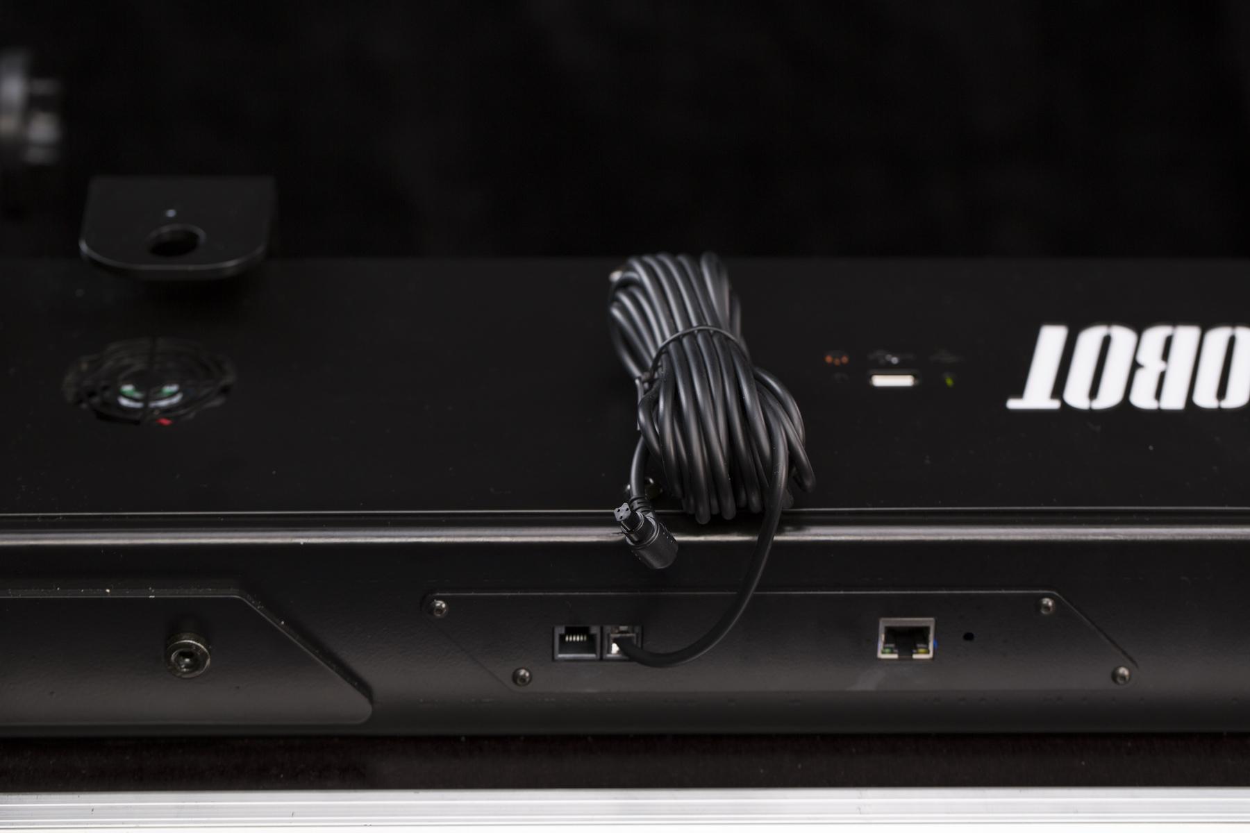
- Pemicu kabel menggunakan soket output terintegrasi 4P4C (RJ9).
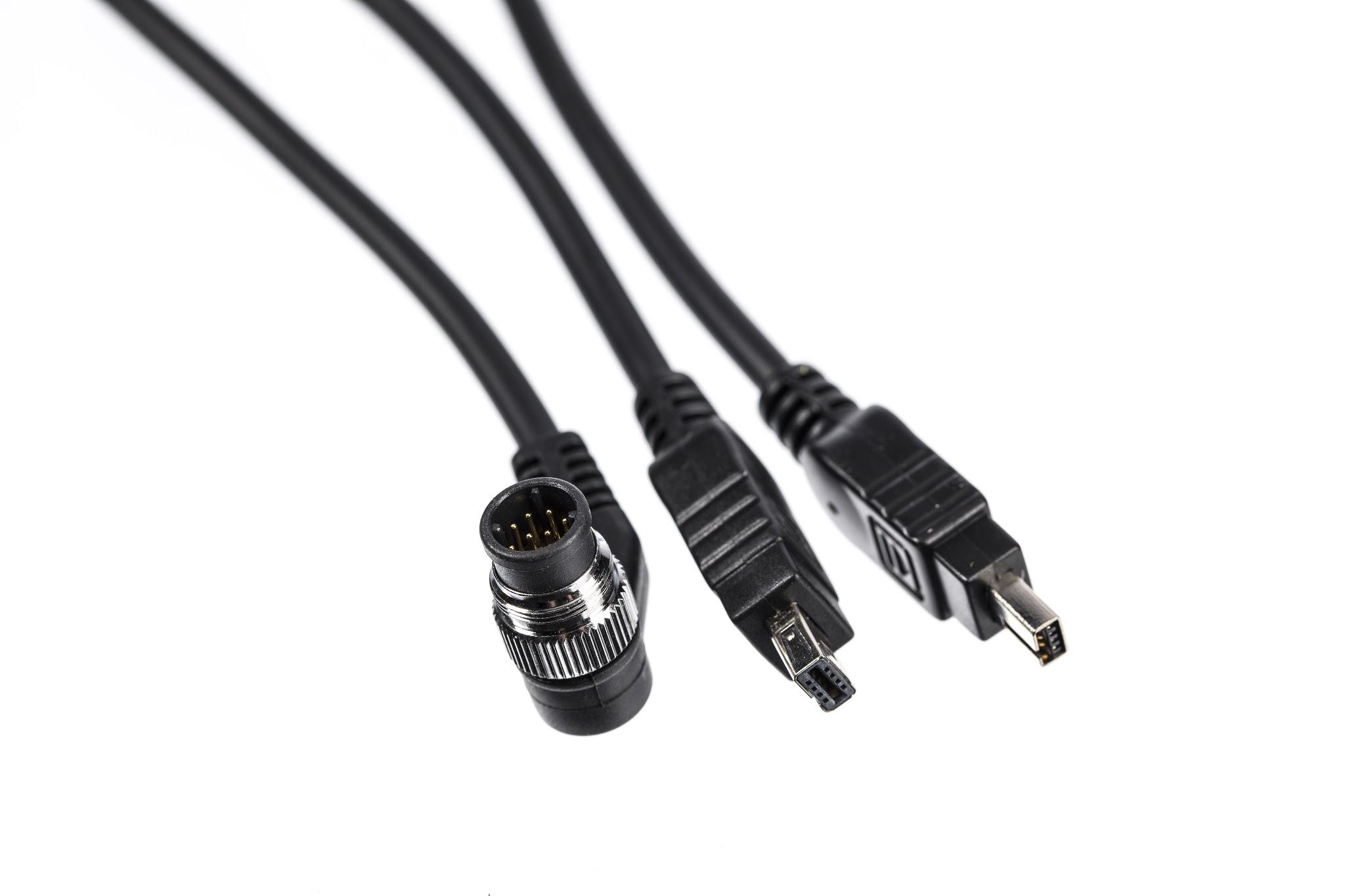
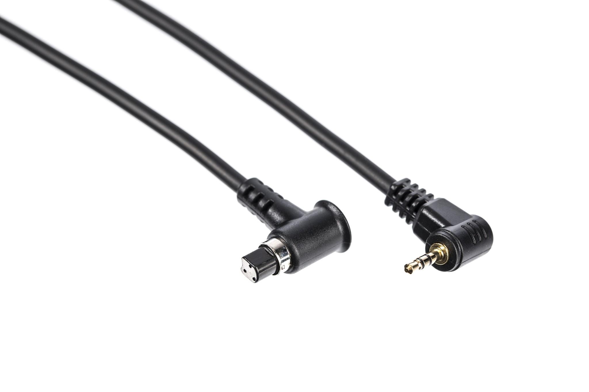
- Pemicu tersedia untuk model kamera yang didukung — lihat PhotoRobot daftar kamera yang kompatibel.
2.2.4. Sakelar Kaki
Foot Switch adalah HID (Human Interface Device) praktis yang diproduksi oleh PhotoRobot untuk mempercepat kinerja Anda. Fungsi operasional apa pun (misalnya, memulai urutan, menjalankan uji coba, memutar piringan, mengatur posisi nol, dll.) dapat ditetapkan ke sakelar sehingga Anda dapat mengakses fungsi secara instan hanya dengan menginjaknya. Dimungkinkan juga untuk menghubungkan dua Foot Switch untuk mendapatkan empat operasi akses mudah. Foot Switch adalah aksesori opsional, disediakan secara terpisah dengan biaya tambahan.
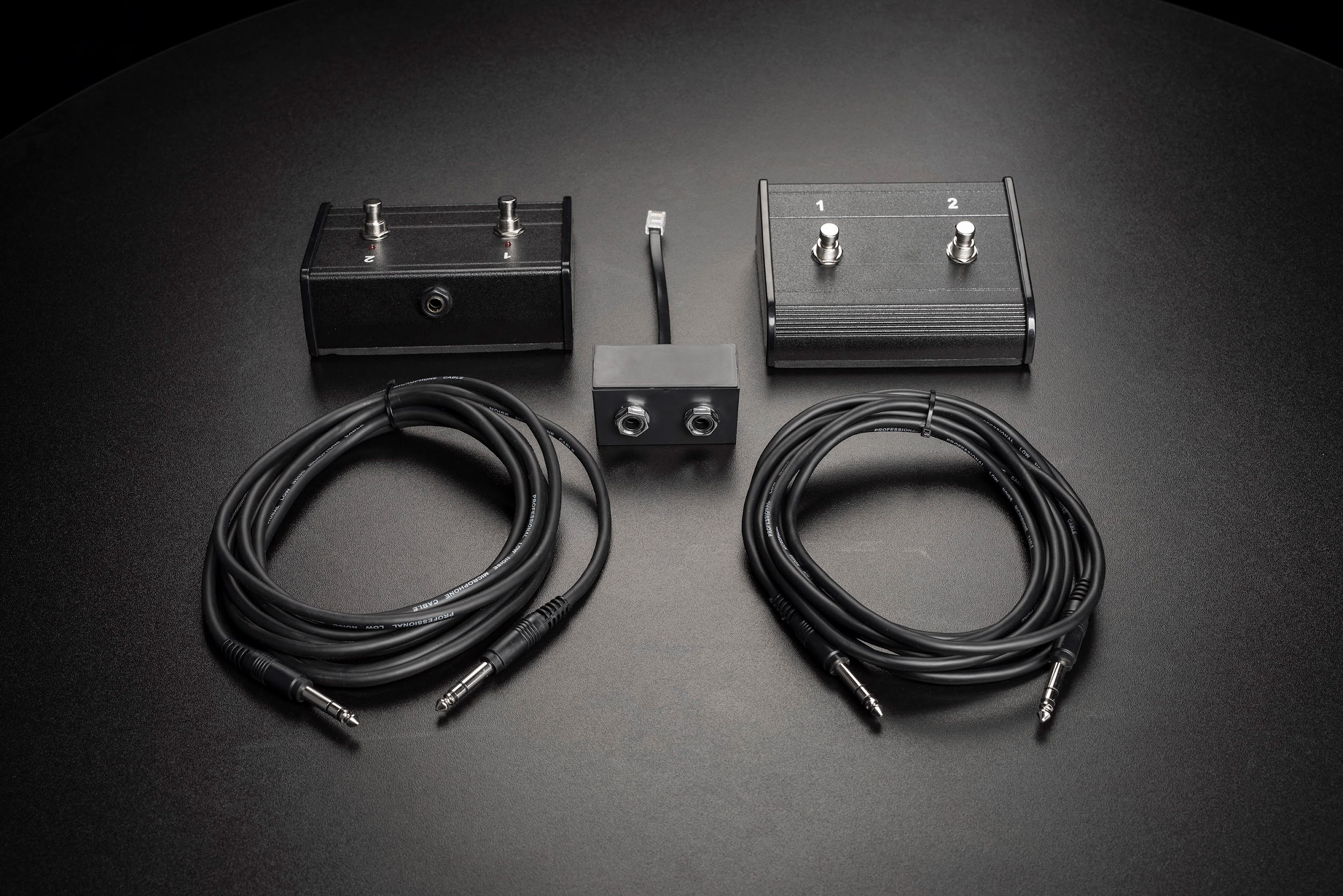
- PhotoRobot “Foot Switch Control Set” terdiri dari sepasang pedal, sepasang kabel jack 6.3 mm, dan reduksi jack 6P6C (RJ12) - 6.3 mm.
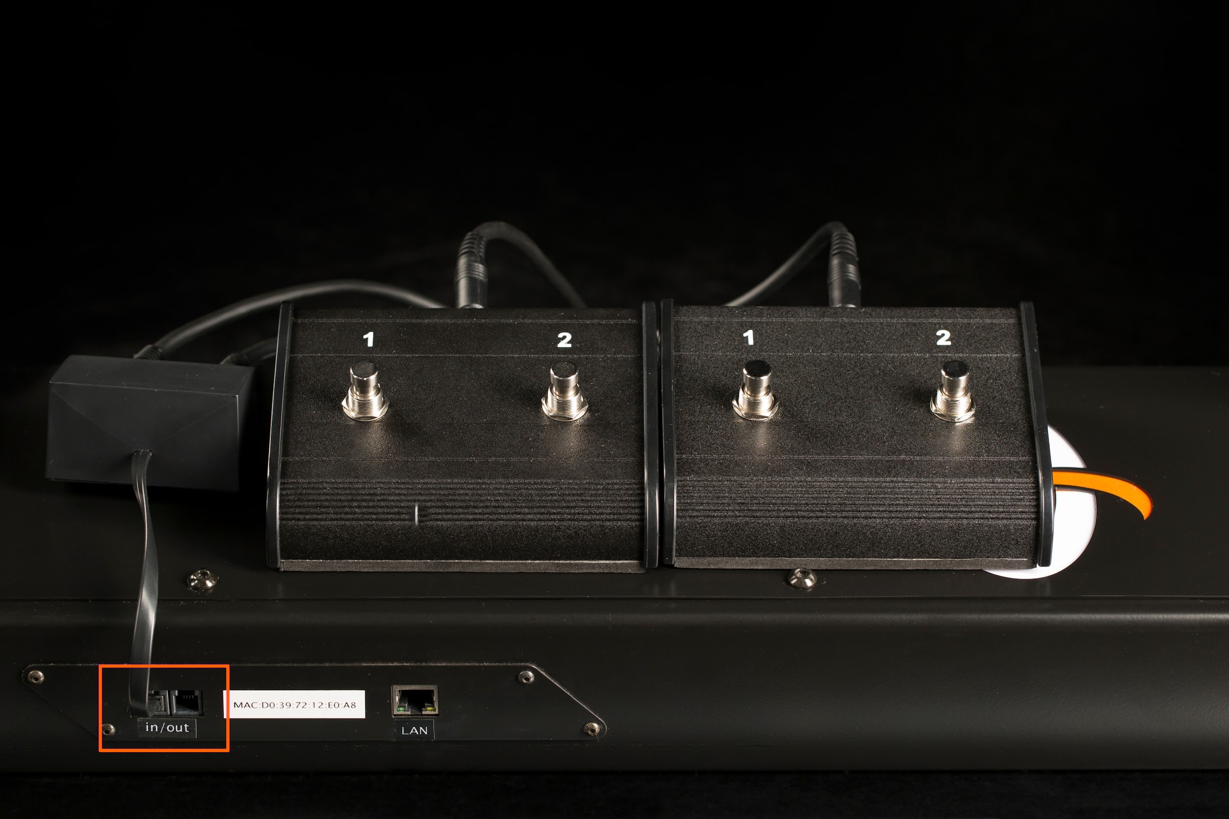
- Soket input 6P6C (RJ12) terintegrasi digunakan untuk mencolokkan Sakelar Kaki ke dalam CASE.
- Aplikasi berbasis browser hanya menampilkan status soket input yang ditentukan. Untuk menetapkan fungsi ke tombol sakelar kaki, perlu menggunakan perangkat lunak canggih (PhotoRobot Controls).
2.2.5. Aksesori Kustom
Anda tidak perlu bergantung hanya pada aksesori yang disediakan oleh PhotoRobot. Soket input dan output dilengkapi dengan jack terdaftar standar – 6P6C (RJ12) & 4P4C (RJ9). Jangan ragu untuk menggunakan Diagram Sirkuit untuk mengadaptasi perangkat apa pun agar berfungsi dengan CASE Anda (misalnya pemicu, sakelar, lampu sinyal, dll.). Namun, perlu diketahui bahwa pengetahuan dasar keselamatan & pemeliharaan listrik diperlukan, dan sangat disarankan Anda meminta bantuan teknisi listrik setempat jika Anda tidak terlatih di bidang ini.
- Jangan ragu untuk mengunduh Diagram Sirkuit di atas untuk digunakan dengan CASE.
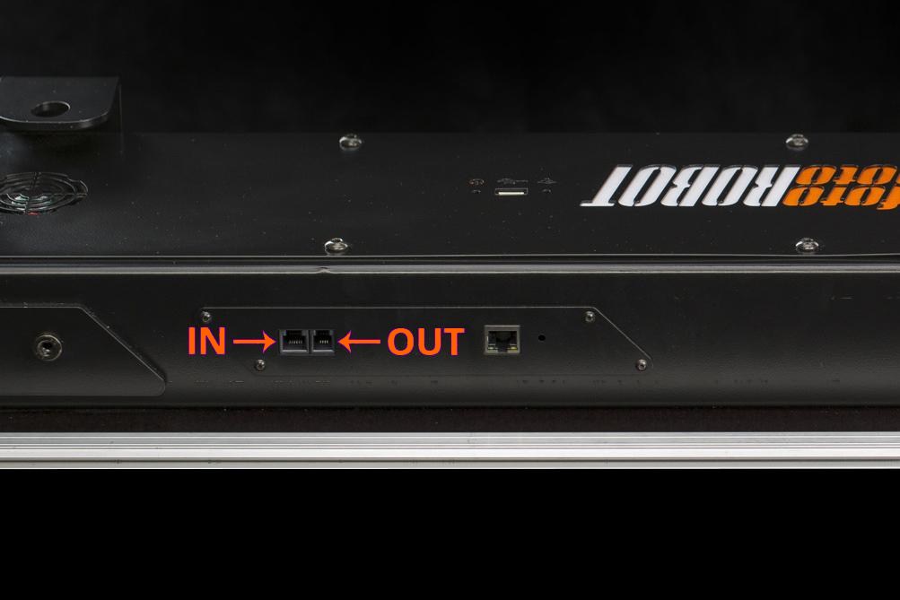
- Soket jack terdaftar IN dan OUT terletak di dasar CASE.
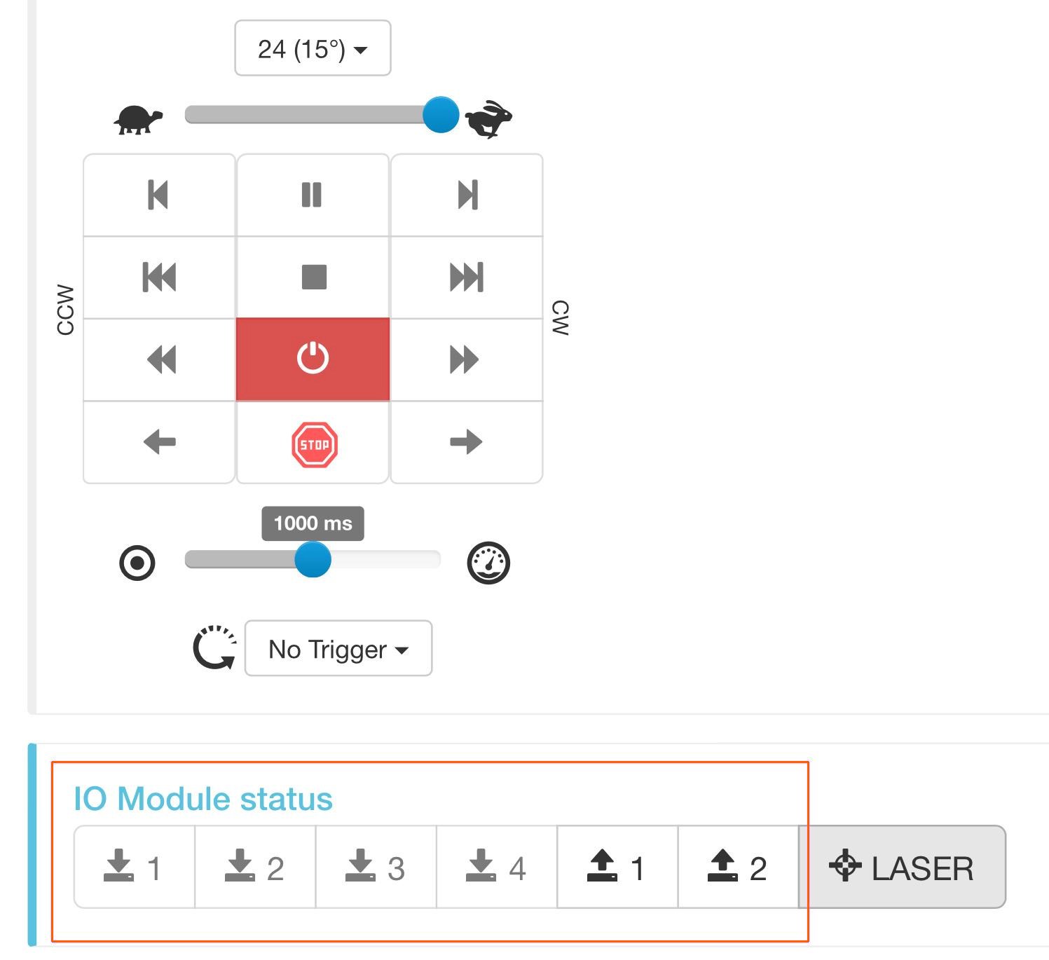
- Perangkat yang disesuaikan dapat dikontrol oleh tombol IN & OUT di bagian bawah aplikasi berbasis browser.
3. Merakit CASE
Membawa CASE dari kondisi terkemas ke kondisi kerja adalah tugas yang mudah dan cepat jika Anda mengikuti empat langkah yang digambarkan di bawah ini. Siapa pun yang mampu mengikat tali sepatu sendiri dapat menguasainya dalam waktu singkat.
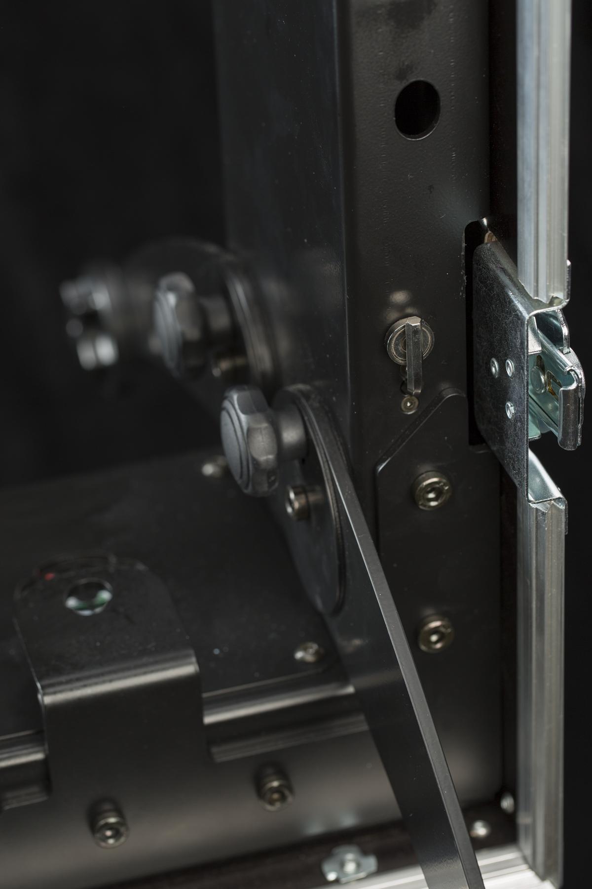
3.1. Buka Sisi-sisinya
Pertama, sebaiknya mulai dengan membuka kotak dan membiarkan bagian-bagian robot tetap terpasang di sisi-sisi sampai Anda membutuhkannya untuk langkah selanjutnya.
- CASE menggunakan kunci putar yang kokoh untuk mengamankan sisi-sisinya.
- Semuanya terpasang erat di sisi CASE.
- Lepaskan dudukan tiang latar belakang dan sisihkan.
- Keluarkan tiang latar belakang.
- Lepaskan karet gelang yang menahan kabel.
- Keluarkan kabel.
- Ikat karet gelang agar tidak hilang.
- Keluarkan pelat pelindung MDF.
- Keluarkan pelat kaca.
- Sisi ini kosong sekarang.
3.2. Pasang Dasar
Untuk memberikan stabilitas maksimum pada CASE agar operasi aman, perlu untuk menambatkan alas dengan menggunakan kaki yang dapat dilipat. Lihat instruksi dengan ilustrasi di bawah ini.
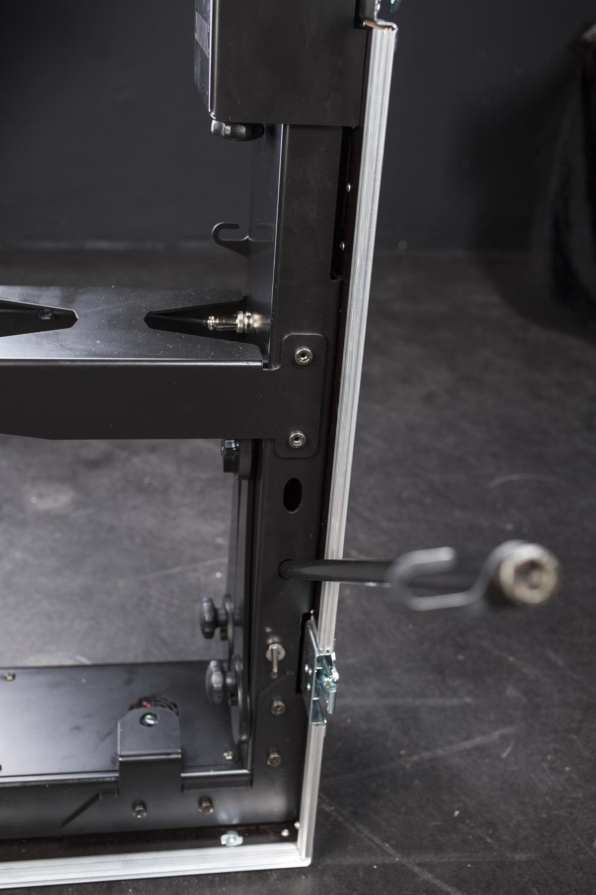
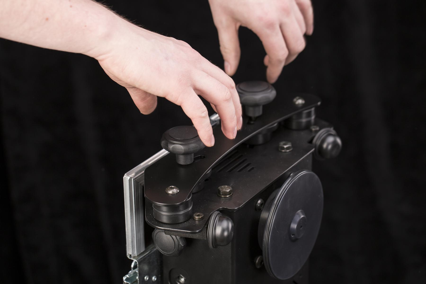
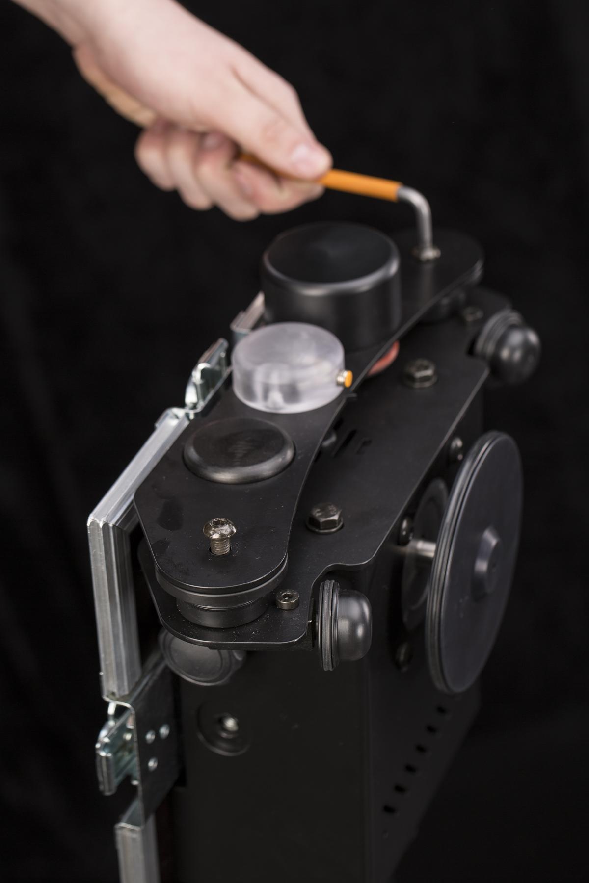
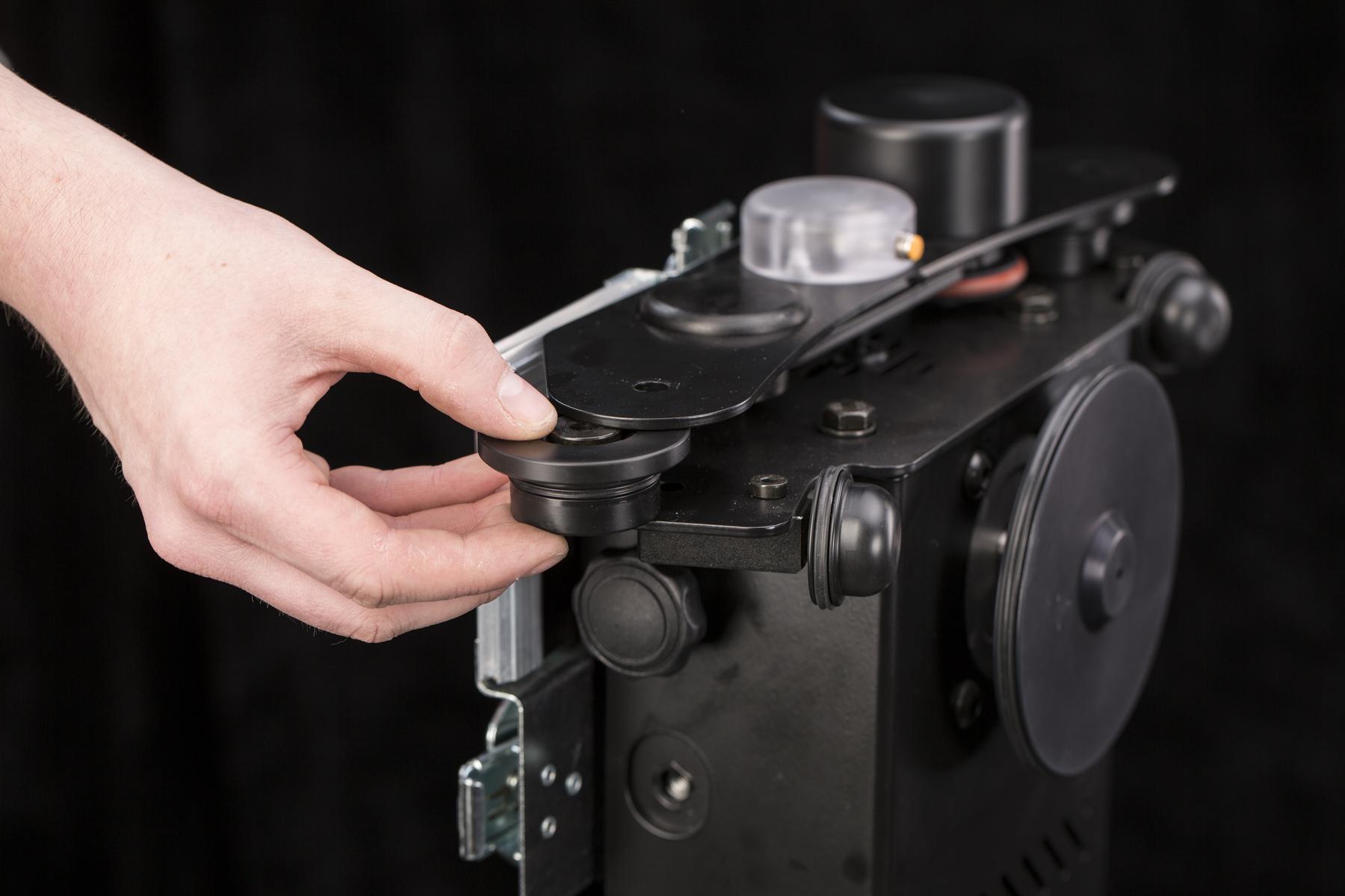
- Untuk membuka kaki-kaki, buka sekrup pengunci dan dorong ke atas.
- Untuk mengamankan kaki yang terlipat, dorong kunci ke bawah dan kencangkan.
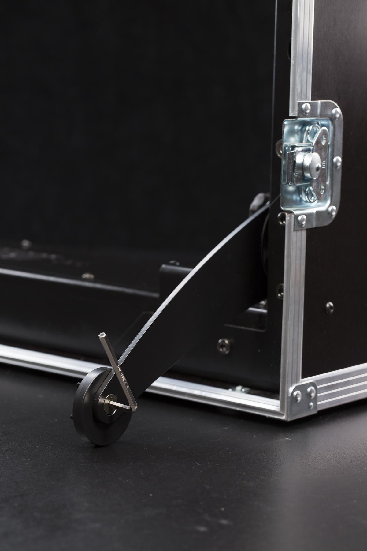
- Untuk meratakan CASE dengan benar, gunakan kunci hex yang terpasang di dasar untuk membuka kunci cincin yang tidak di tengah.
- Selanjutnya, sesuaikan stabilitas CASE dengan memutar cincin di luar pusat. Saat Anda menemukan posisi terbaik, kencangkan cincin menggunakan kunci hex.
3.3. Pasang Pelat Kaca
Pemasangan pelat kaca sangat sederhana. Bagian tersulit dari pemasangan pelat adalah tidak mengotori kaca saat memasangnya ke alas. Disarankan untuk menggunakan sepasang sarung tangan bersih saat memegang pelat kaca.
Catatan: Generasi terbaru CASE 850 (versi sensor optik, tanpa cangkir hisap kalibrasi) menggunakan pelat kaca dengan bevel kecil yang digiling di tepinya. Masukkan pelat sehingga bevel ini berada di bagian bawah, di atas sensor optik tersembunyi yang membaca posisi pelat. Pelat sebelumnya tanpa bevel tidak memiliki orientasi yang diperlukan.
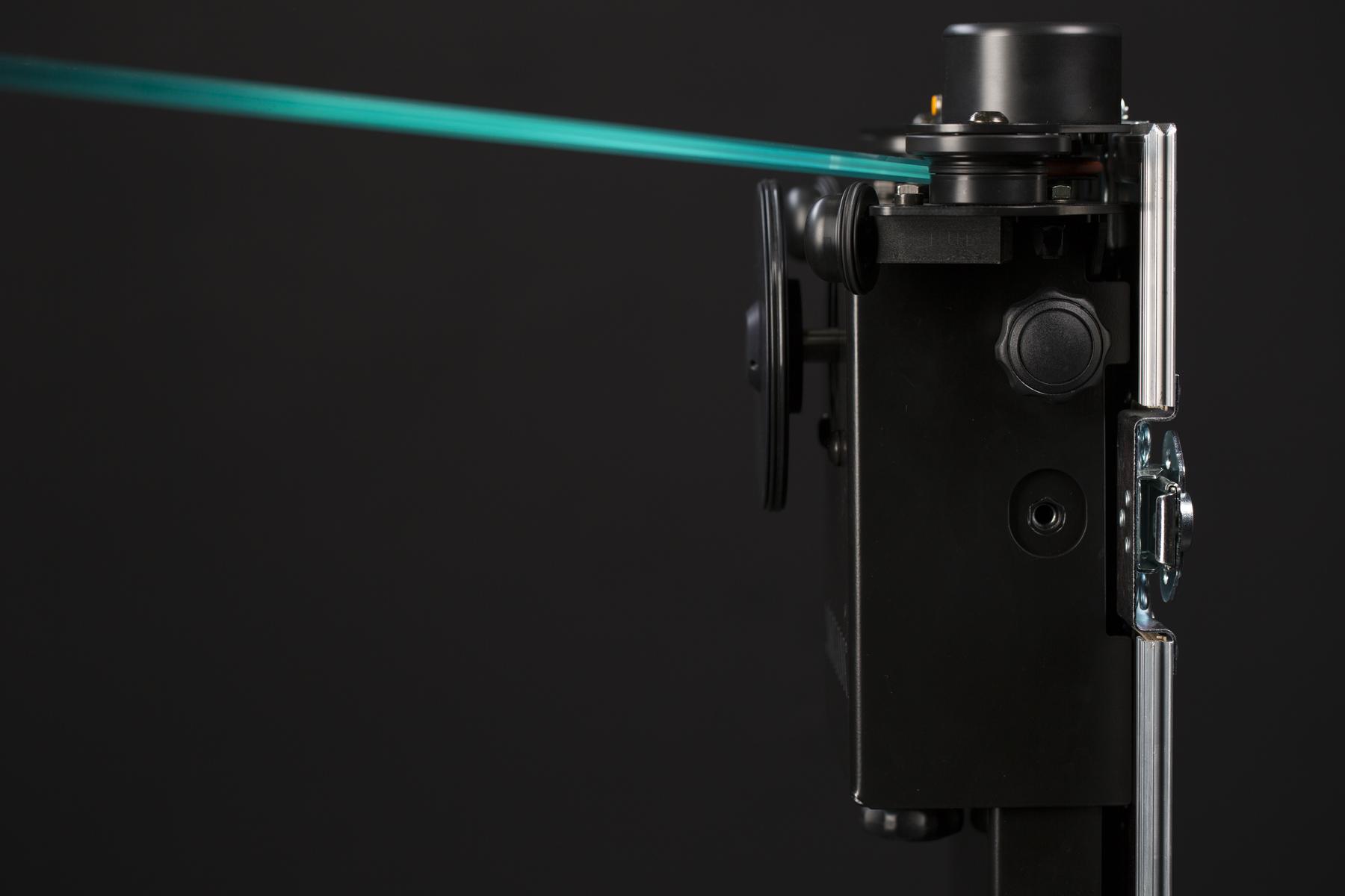
- Tempatkan piringan kaca di sisi tempat encoder berada. Anda perlu sedikit memiringkannya agar tepinya masuk di bawah roda pemandu.
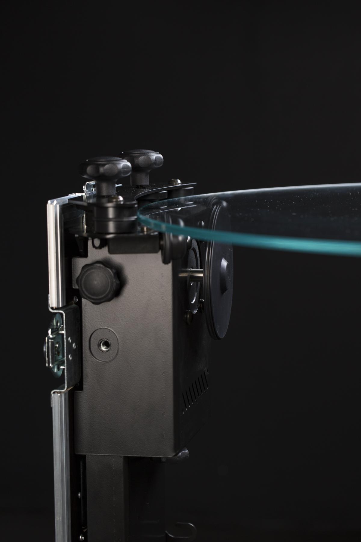
- Letakkan pelat kaca di sisi berlawanan dari CASE.
- Pelat kaca miring berada di bawah roda pemandu di sisi berlawanan dari CASE.
- Pelat kaca diletakkan.
- Pelat kaca terkunci pada posisinya oleh satu set roda pemandu yang dapat digerakkan.
- Roda pemandu yang dapat digerakkan mengunci pelat kaca dengan aman pada posisinya.
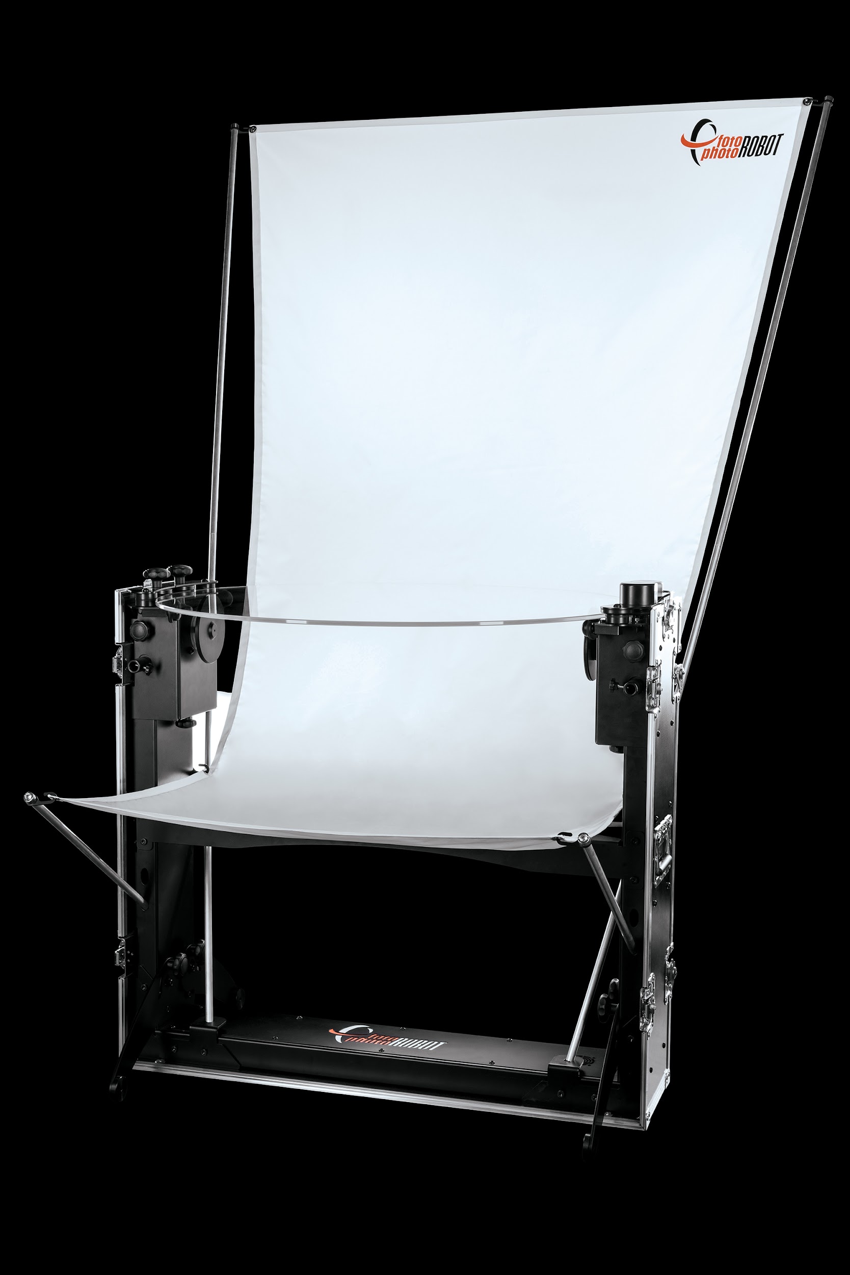
3.4 Pasang Latar Belakang
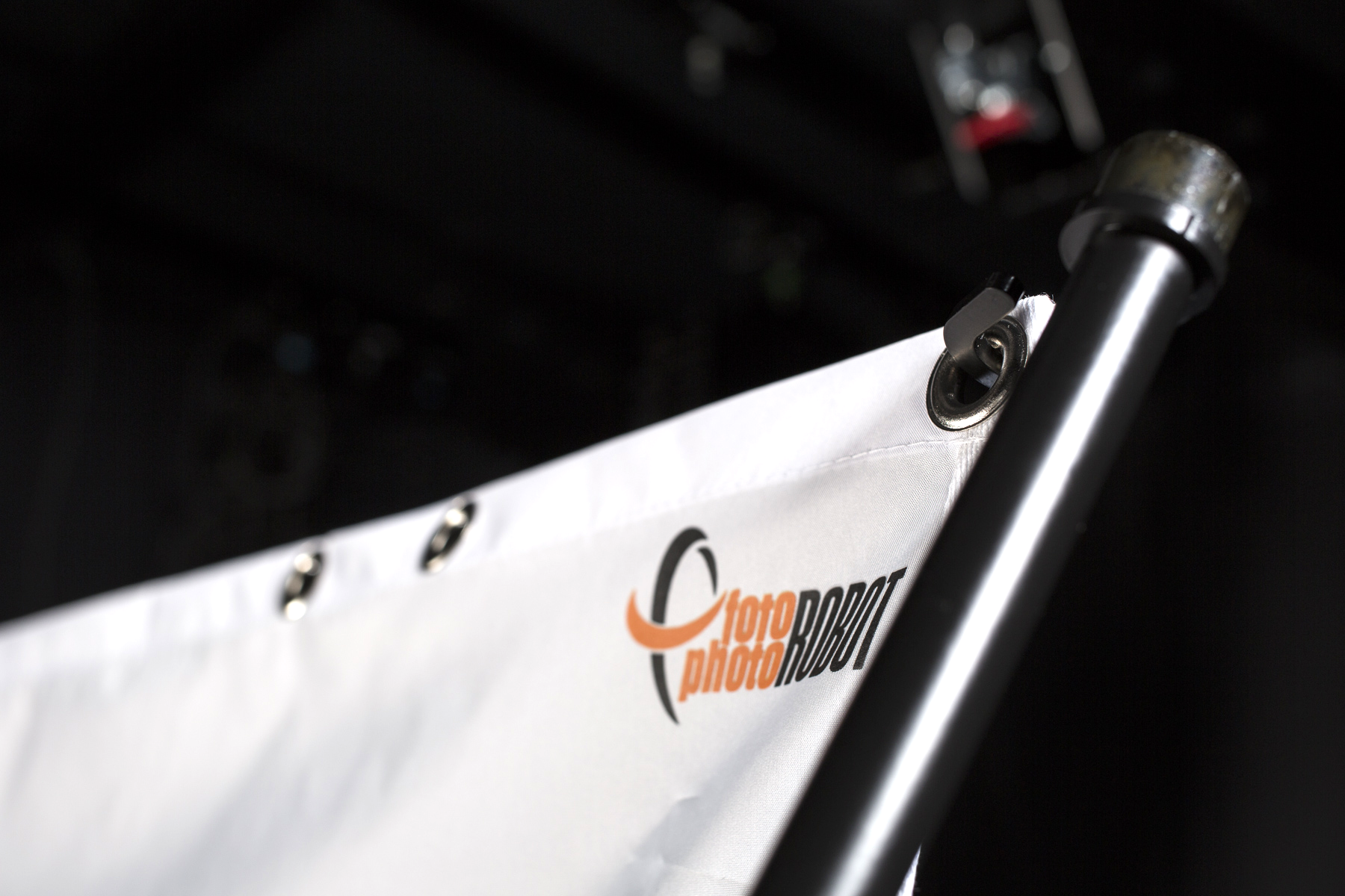
Jika Anda ingin memotret dengan latar belakang putih bersih, kami menyediakannya untuk kenyamanan Anda sebagai bagian integral dari CASE. Bahan dan bentuknya memudahkan untuk mencapai latar belakang putih bersih tanpa perlu pasca-produksi. Pastikan untuk menangani latar belakang dengan hati-hati, mengambil tindakan pencegahan untuk mencegah kerutan atau perubahan warna. Meskipun dimungkinkan untuk membersihkan dan menyetrika latar belakang, hal itu dapat mengubah kualitas dan masa pakainya.
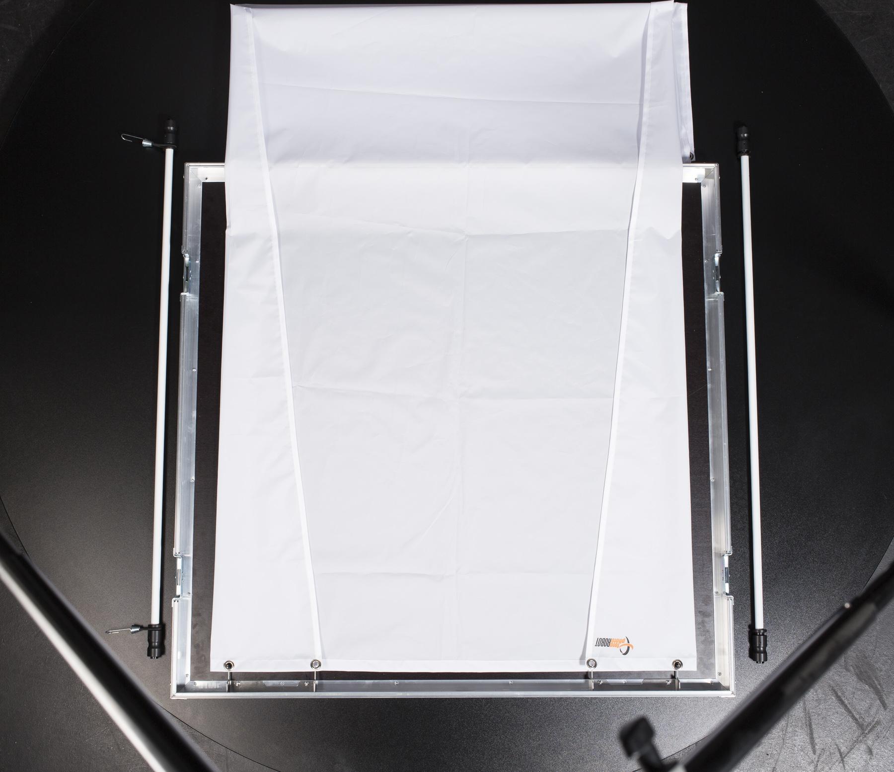
- Masukkan tiang yang lebih panjang melalui dua lubang tali di kedua sisi CASE. Gunakan tiang tanpa pengait.
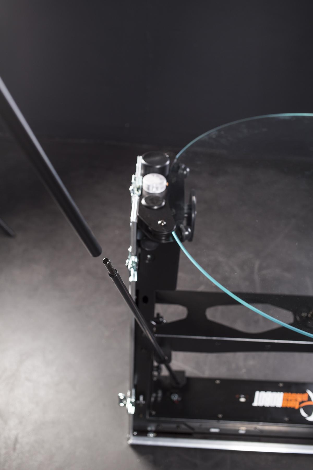
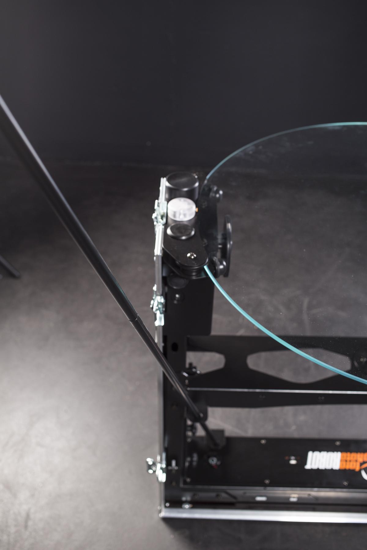
- Pasang tiang yang lebih panjang dengan kait ke tiang yang sudah terpasang pada CASE.
- Masukkan tiang pendek dengan pengait ke dalam lubang di kedua sisi di dasar CASE-nya.
- Foto-foto di atas menunjukkan tiang latar belakang yang sudah siap dan dengan latar belakang yang digantung.
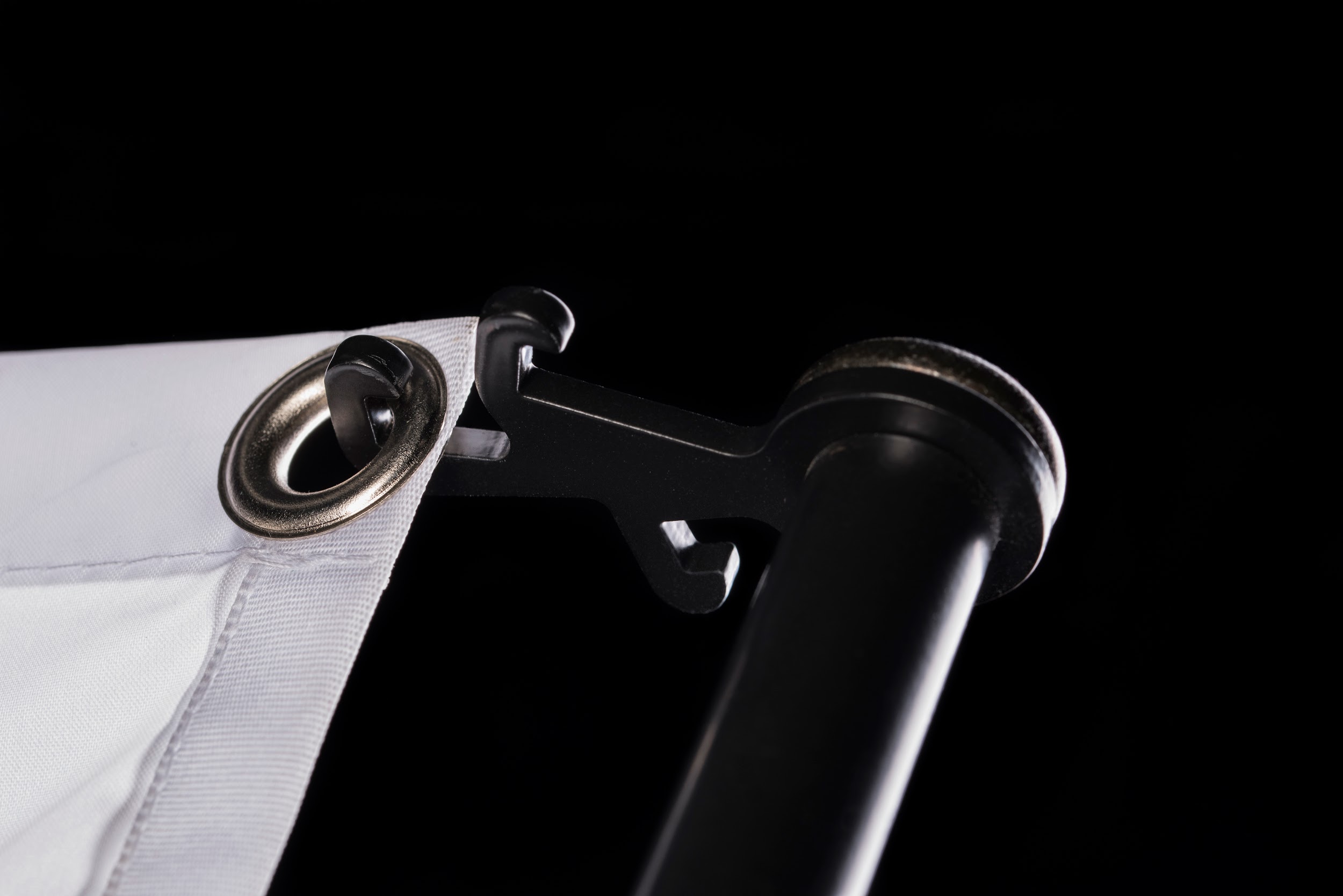
- Pengait tiga kali lipat memberikan peregangan latar belakang yang mudah & ramping.
- Untuk menggantung latar belakang, mulailah dengan mengaitkan bagian atas terlebih dahulu.
- Selanjutnya, pasang ujung latar belakang yang berlawanan.
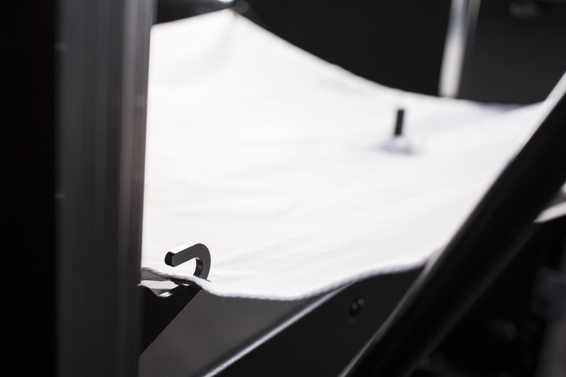
- Kemudian, pasang latar belakang di dasar CASE.
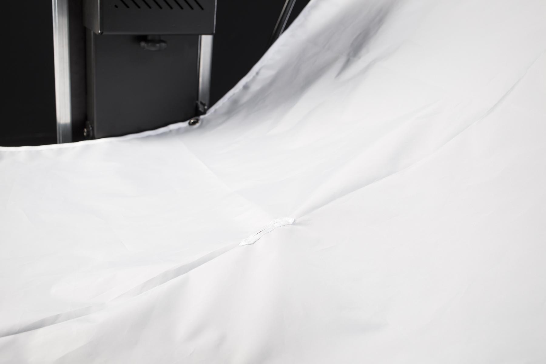
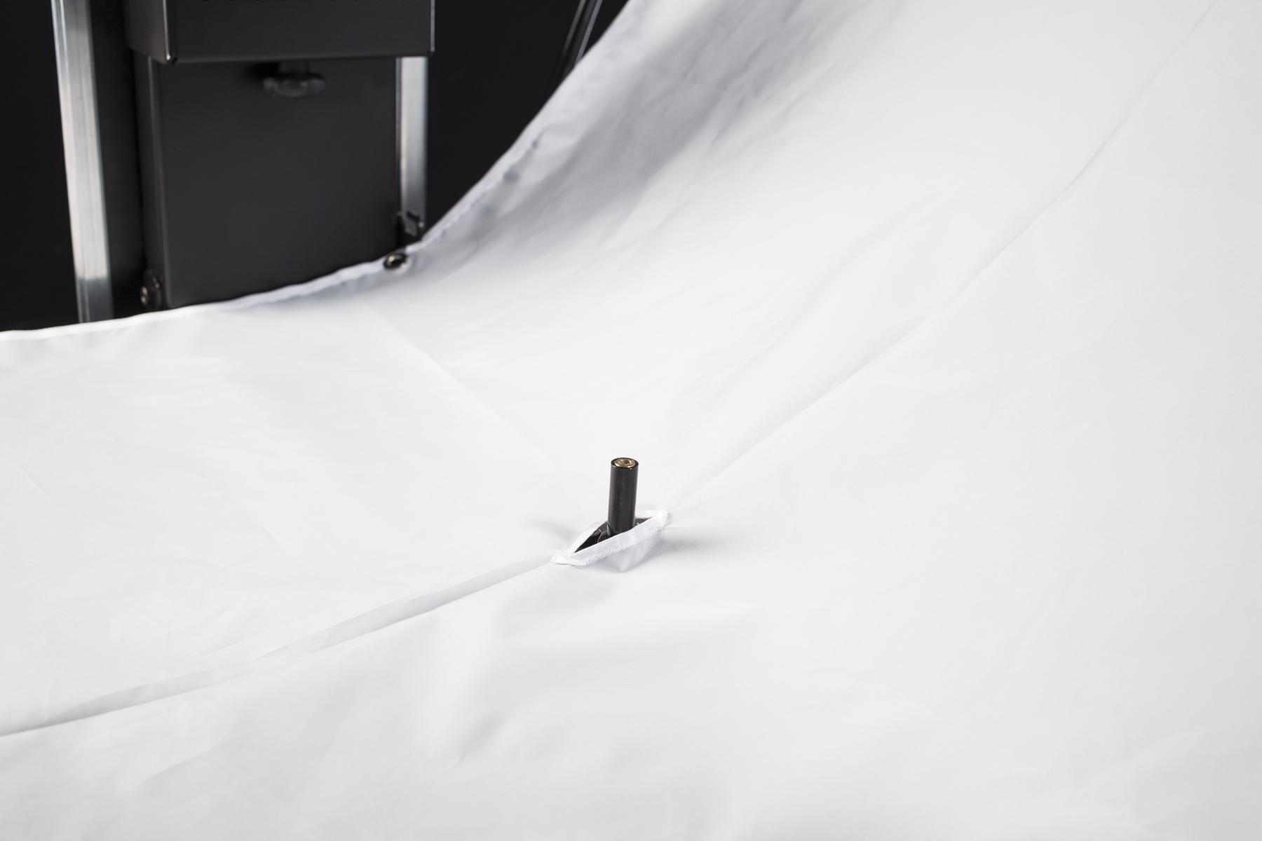
- Terakhir, pastikan laser terpapar melalui celah di latar belakang.
4. Mengoperasikan CASE
CASE adalah mekanisme canggih yang membutuhkan pengetahuan dasar fotografi untuk pengoperasian yang berhasil. Bab-bab berikut memberikan semua informasi yang diperlukan untuk berhasil.
4.1. Colokkan
CASE dirancang untuk bekerja dengan pasokan listrik utama 100-240 V. Ini menggunakan coupler C13/C14 standar dengan steker Eropa, Inggris, atau AS. Untuk alasan keamanan, CASE harus dimatikan saat mencolokkan kabel daya.
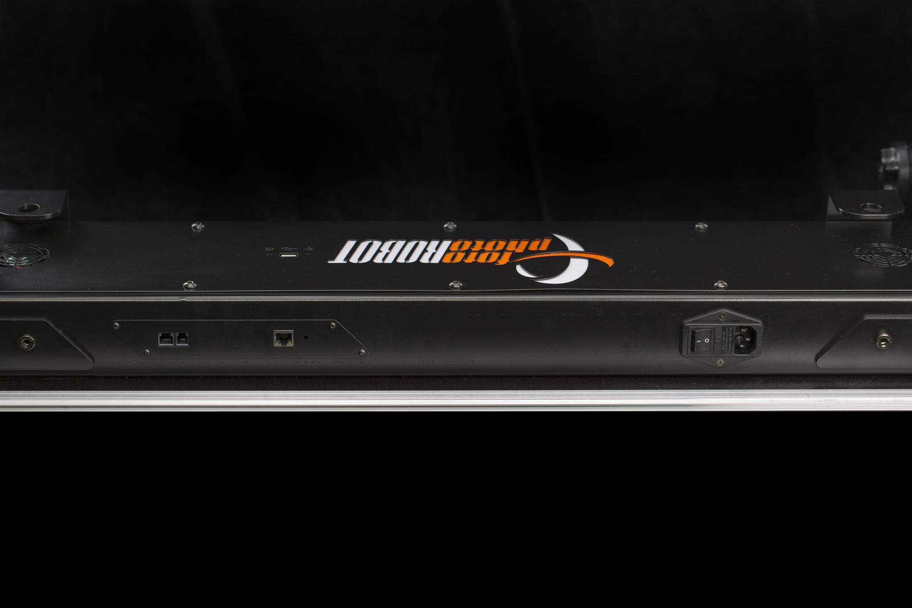
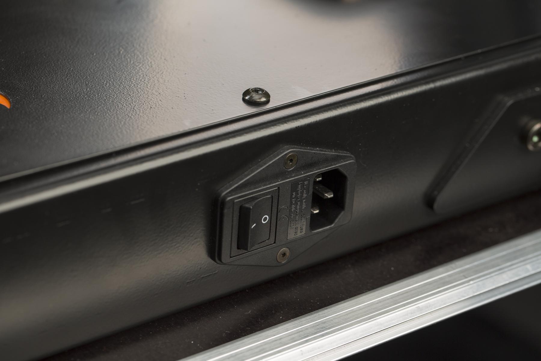
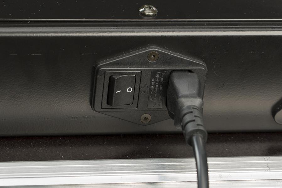
- Soket daya terletak di dasar CASE (seperti pada 3 foto di atas).
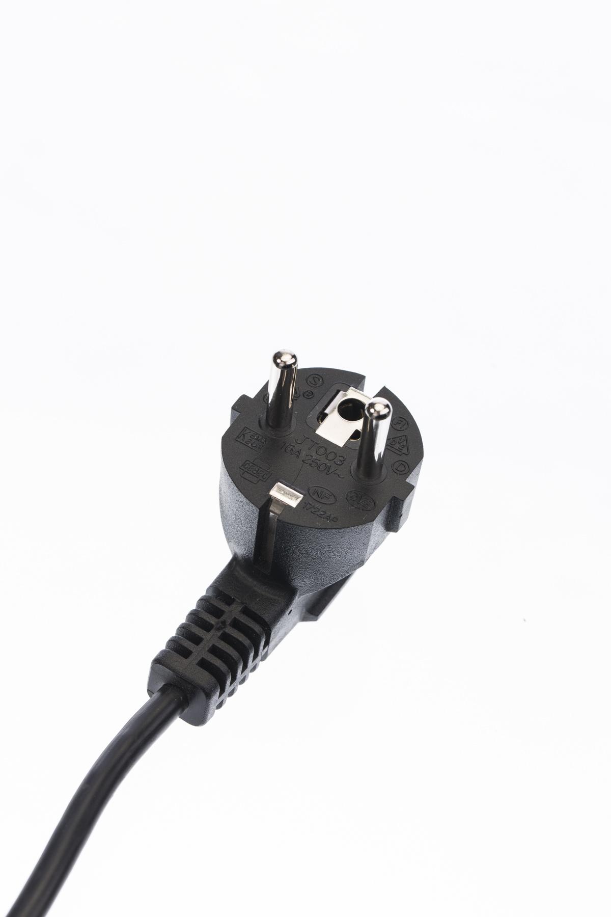
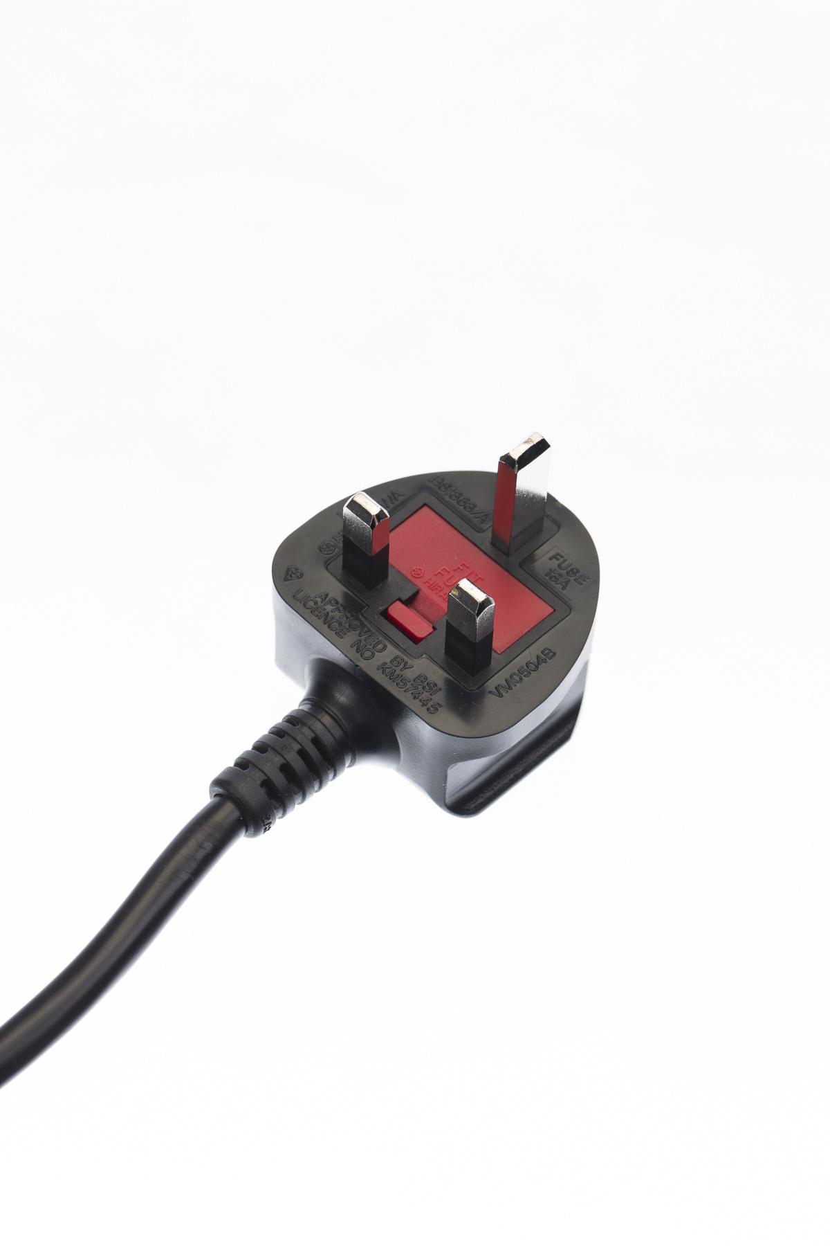
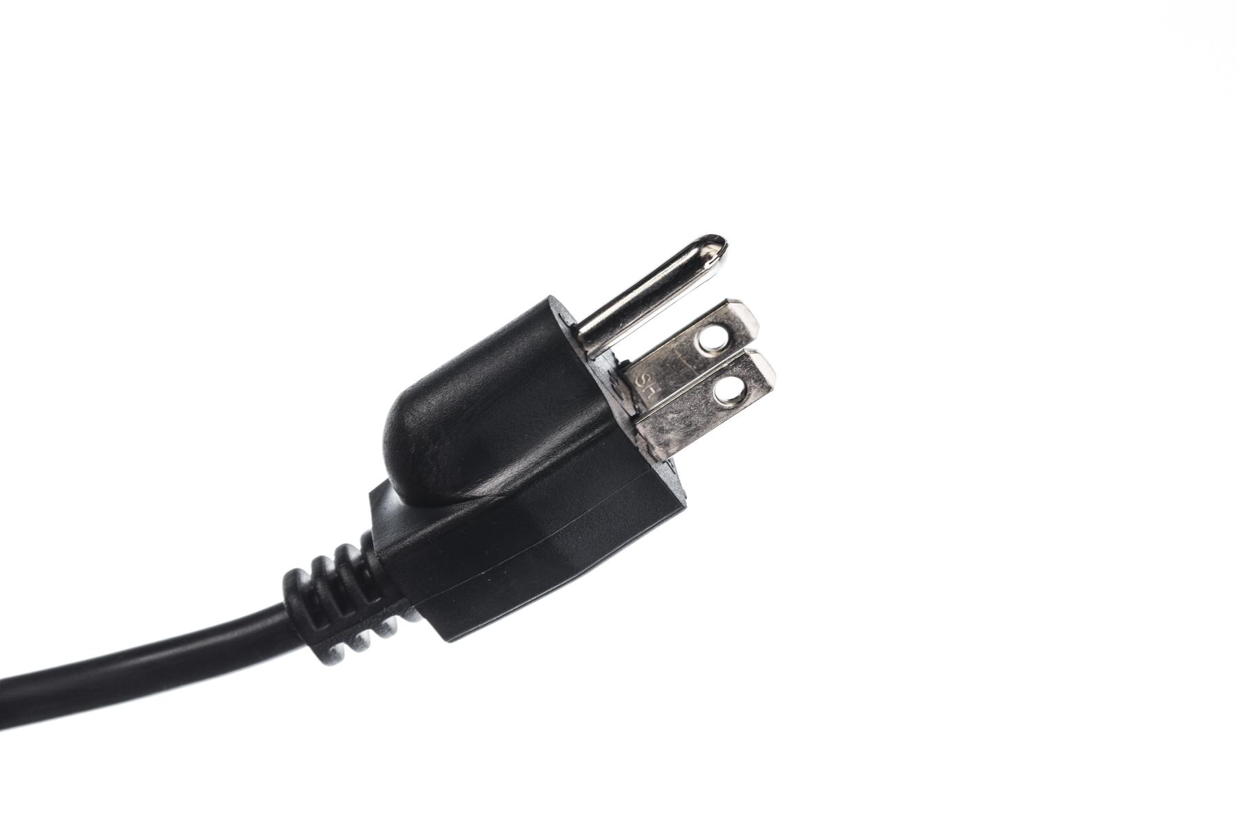
- PhotoRobot akan menyediakan soket listrik EU, UK, atau US, tergantung wilayah Anda.
4.2. Nyalakan
Untuk menyalakan CASE, sakelar daya terletak di sebelah soket daya utama.
Harap CATATAN: Saat menyalakan CASE dengan konektivitas Wi-Fi, dibutuhkan sekitar 2 menit untuk mem-boot unit kontrol, atau 30 detik saat terhubung melalui LAN.
4.2.1. Indikasi lampu LED
Lampu LED Daya (merah/hijau > 3 pin)
- Lampu kuning dengan pola detak jantung hijau berarti sistem sedang booting.

- Lampu hijau menyala berarti sistem sedang berjalan.

- Lampu merah menyala berarti ada kesalahan perangkat keras.
- Lampu hijau berkedip berarti perangkat sedang bergerak.
- Lampu merah berkedip berarti 'tidak terautentikasi'.
Lampu LED Wi-Fi (biru > 2 pin)
- Lampu biru mati berarti Wi-Fi tidak terhubung.
- Lampu biru berkedip berarti Wi-Fi sedang terhubung.

- Lampu biru menyala berarti Wi-Fi terhubung.
4.3. Hubungkan
CASE dibangun di sekitar unit kontrol PhotoRobot generasi terbaru, dioperasikan oleh PhotoRobot Controls — perangkat lunak kami yang dirilis terutama untuk macOS dan juga untuk Windows (meskipun, kami merekomendasikan macOS untuk pengalaman terbaik). Aplikasi pendamping, PhotoRobot Touch, dapat berfungsi sebagai kamera nirkabel untuk versi macOS. Integrator tingkat lanjut dapat secara alternatif mengontrol unit langsung melalui API-nya. Untuk mengoperasikan CASE, itu harus dihubungkan melalui LAN atau jaringan nirkabel sehingga aplikasi pengontrol dapat berkomunikasi dengan robot. CASE juga dapat membuat jaringan Wi-Fi sendiri melalui modul USB. Koneksi internet tidak diperlukan untuk mengoperasikan CASE, tetapi internet diperlukan untuk memperbarui firmware. Bab-bab berikut menjelaskan cara menghubungkan CASE.
4.3.1. Aplikasi Antarmuka Pengguna Berbasis Peramban
Aplikasi antarmuka pengguna berbasis browser adalah bagian dari unit kontrol terintegrasi CASE. Aplikasi ini dapat diakses dari browser web di perangkat apa pun. Aplikasi ini tidak memiliki kemampuan untuk menyesuaikan pengaturan kamera dan pencahayaan, tetapi menambahkan mobilitas dan fleksibilitas luar biasa pada fotografi robotik. Untuk menghubungkan CASE ke Antarmuka Pengguna Browser, baik CASE maupun perangkat pengontrol harus berada dalam jaringan yang sama melalui jaringan LAN, WLAN, atau Wi-Fi yang disediakan oleh modul Wi-Fi yang terpasang di CASE.
Catatan: Antarmuka berbasis browser adalah antarmuka layanan — ini tidak dimaksudkan untuk fotografi produksi. Dengan lisensi API mesin, perilaku ini dapat diperluas untuk memungkinkan pengambilan gambar produksi melalui antarmuka layanan.
4.3.1.1. LAN
CASE memiliki soket 8P8C (RJ45) terintegrasi untuk menghubungkan CASE menggunakan kabel ethernet standar.
- Temukan soket 8P8C (RJ45) untuk koneksi jaringan yang terletak di bagian bawah dasar CASE.
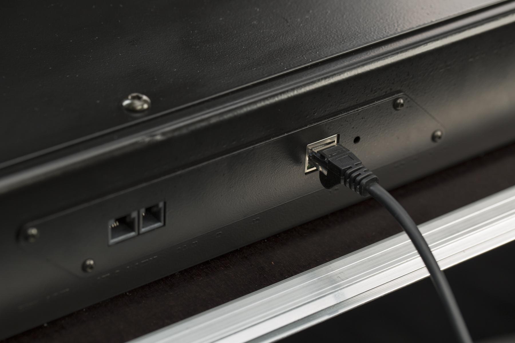
- Kabel ethernet standar dapat digunakan untuk menyambungkan ke CASE.
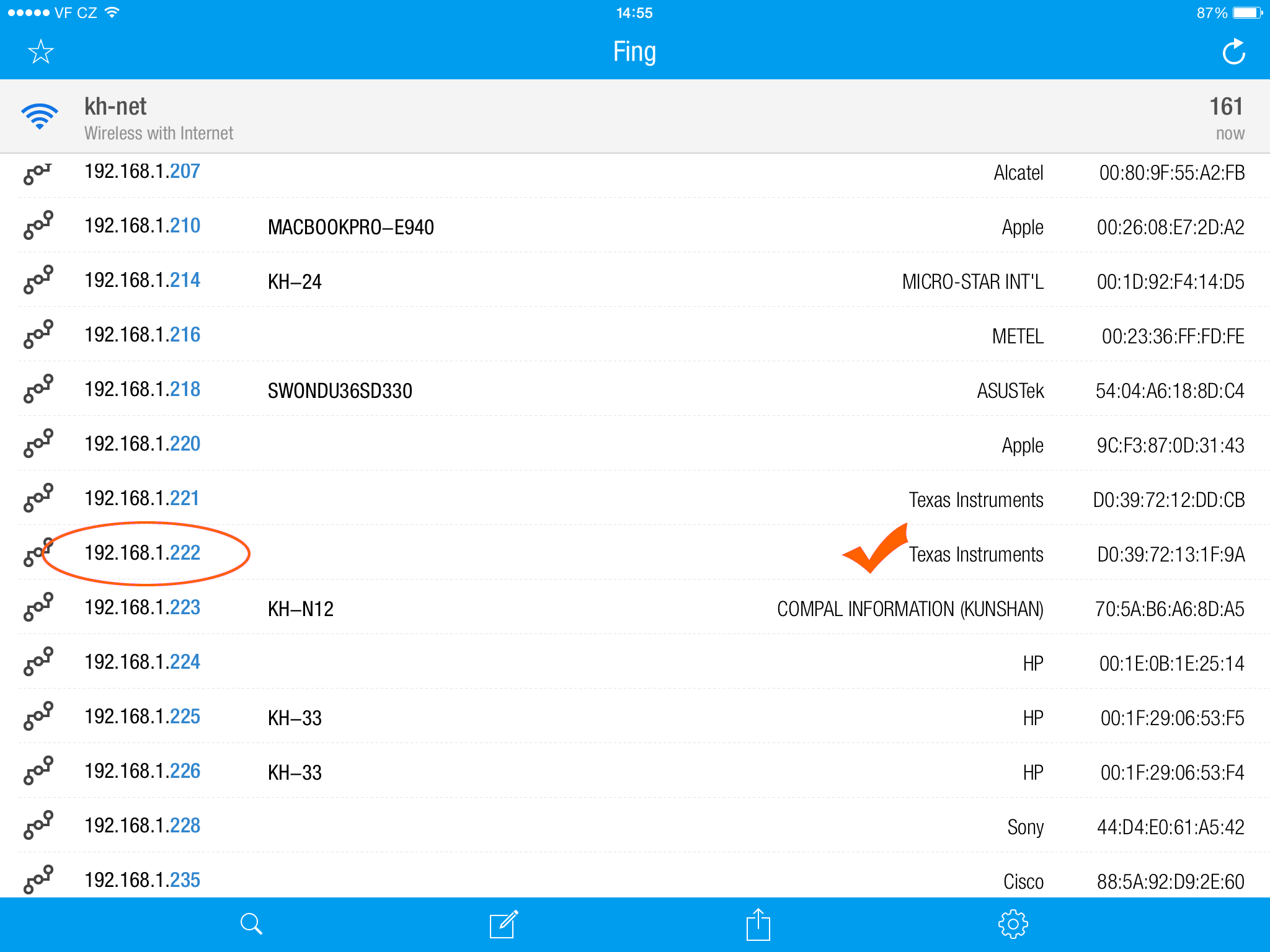
- Penting untuk menemukan alamat IP CASE untuk menghubungkannya ke Aplikasi UI berbasis Browser. Anda dapat menggunakan pemindai IP apa pun, seperti aplikasi seluler Fing. Dalam daftar alamat IP, cari “Texas Instruments” (contoh di atas).
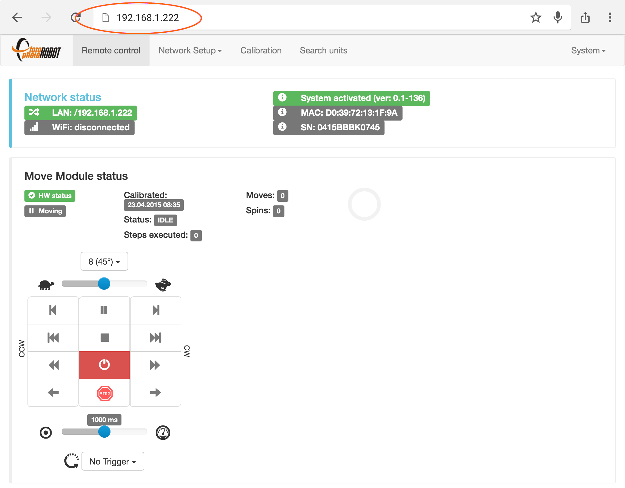
- Untuk meluncurkan Aplikasi UI berbasis Browser, masukkan alamat IP CASE ke browser web apa pun. Untuk mempelajari lebih lanjut tentang mengontrol CASE menggunakan aplikasi ini, silakan merujuk ke bab 4.9.2 - Kontrol CASE.
4.3.1.2. Jaringan Wi-Fi yang dibuat oleh CASE (mode AP)
Untuk membuat jaringan nirkabel CASE sendiri, perlu menggunakan modul Wi-Fi USB yang tersedia sebagai aksesori opsional.

- Catatan: Mungkin perlu untuk mematikan data seluler agar dapat menghubungkan perangkat Anda ke CASE melalui Wi-Fi.
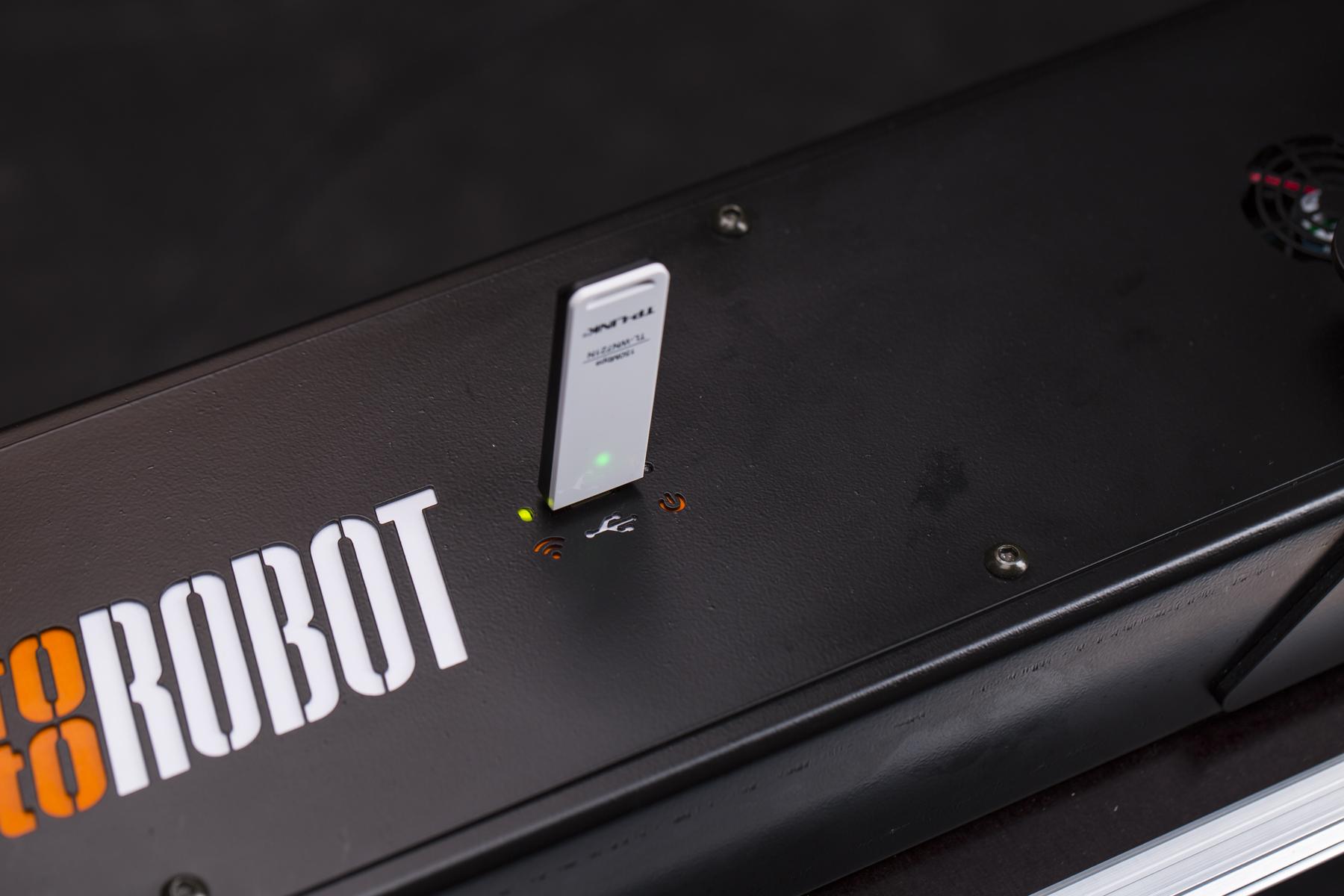
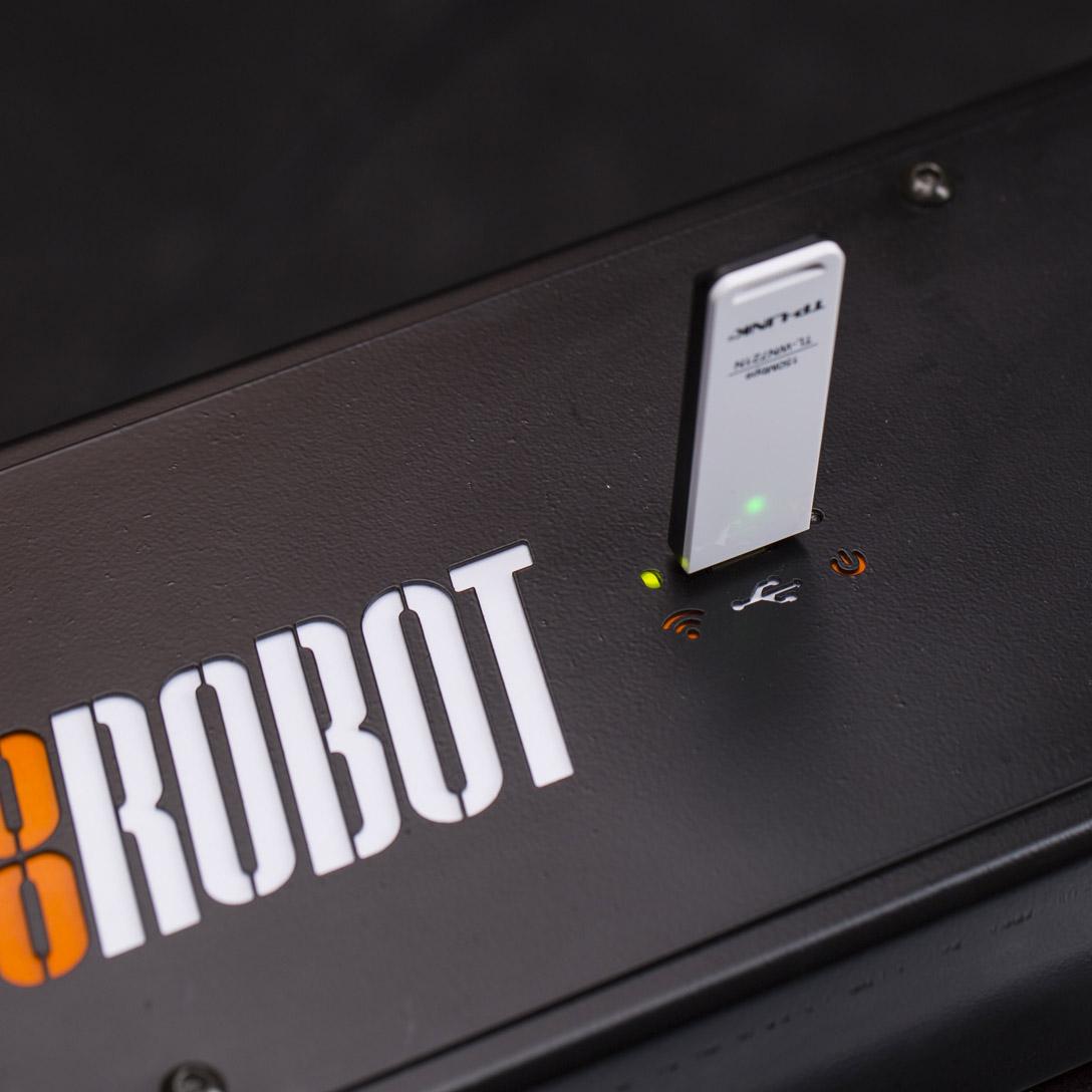
- Colokkan modul Wi-Fi ke soket USB CASE yang terletak di sisi atas dasar mesin. Inisiasi yang berhasil akan ditunjukkan dengan LED hijau berkedip.

- Cari jaringan Wi-Fi bernama “CASE_SerialNumber” di komputer atau perangkat seluler Anda.
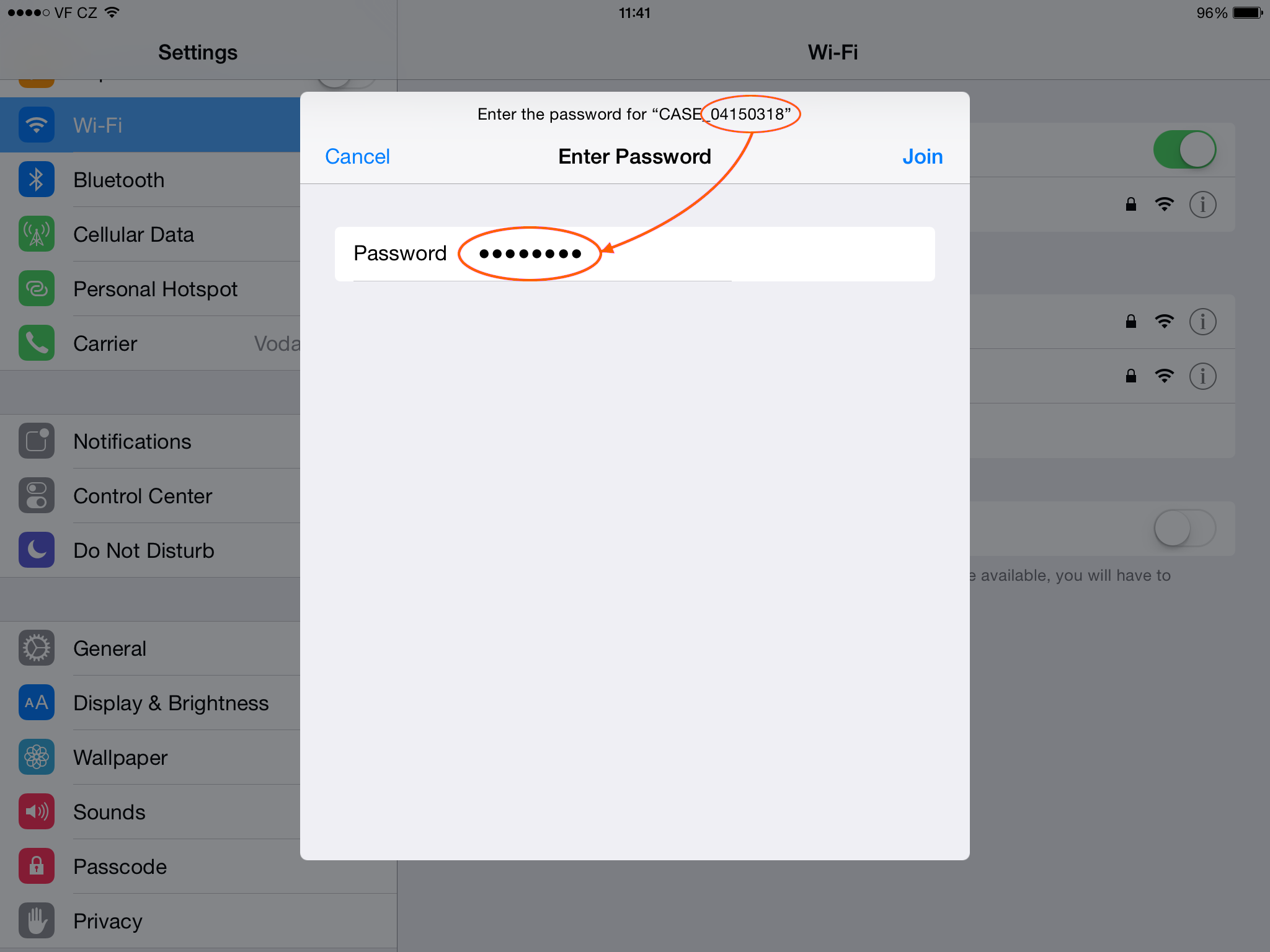
- Untuk terhubung ke jaringan “CASE_SerialNumber”, gunakan SerialNumber sebagai kata sandi (dalam contoh di atas: 04150318).

- Ketika Wi-Fi CASE terhubung ke perangkat Anda, Anda siap untuk mulai mengontrol CASE. Secara default, Wi-Fi CASE menyiarkan pada saluran No. 9.

- Untuk meluncurkan Aplikasi Antarmuka Pengguna berbasis Web, ketik 11.11.11.11 ke jendela alamat browser Anda. Untuk mempelajari lebih lanjut tentang mengontrol CASE menggunakan aplikasi ini, silakan merujuk ke bab 4.9.2 - Kontrol CASE.
CATATAN: Saat menyalakan CASE dengan konektivitas Wi-Fi, dibutuhkan sekitar 2 menit untuk mem-boot unit kontrol.
4.3.1.3. Jaringan Wi-Fi yang ada (mode klien)
Anda dapat menghubungkan CASE ke jaringan nirkabel yang ada menggunakan Modul Wi-Fi USB dari aksesori opsional. Dengan cara ini, perangkat pengontrol Anda (misalnya, komputer atau perangkat seluler) dapat mengoperasikan CASE dan tetap terhubung ke jaringan reguler Anda untuk mengakses internet, printer, drive NAS, dan periferal jaringan lainnya.
Untuk melakukan ini, Anda harus terlebih dahulu terhubung ke jaringan Wi-Fi CASE yang disediakan oleh modul USB. Prosedur ini dijelaskan dalam bab sebelumnya 4.3.1.2 - Jaringan Wi-Fi yang dibuat oleh CASE.

- Setelah Anda terhubung ke Wi-Fi yang disediakan oleh modul USB yang dicolokkan ke CASE dan antarmuka pengguna web diluncurkan melalui alamat IP 11.11.11.11, buka pengaturan Wi-Fi di menu Pengaturan Jaringan.

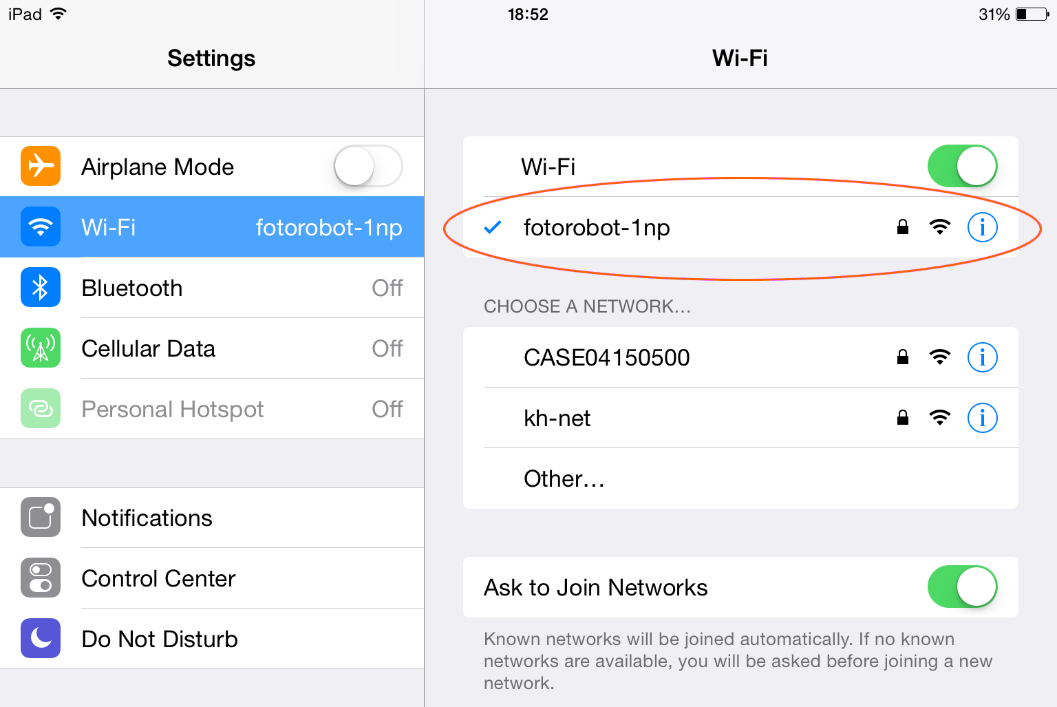
- Dalam daftar jaringan nirkabel, pilih jaringan yang ingin Anda sambungkan ke CASE.

- Selanjutnya, masukkan kata sandi jaringan nirkabel yang Anda pilih.

- Dalam contoh di atas, jaringan nirkabel “fotorobot-1np” berhasil terhubung.
- Hubungkan perangkat Anda ke jaringan nirkabel yang sama yang terhubung ke CASE.
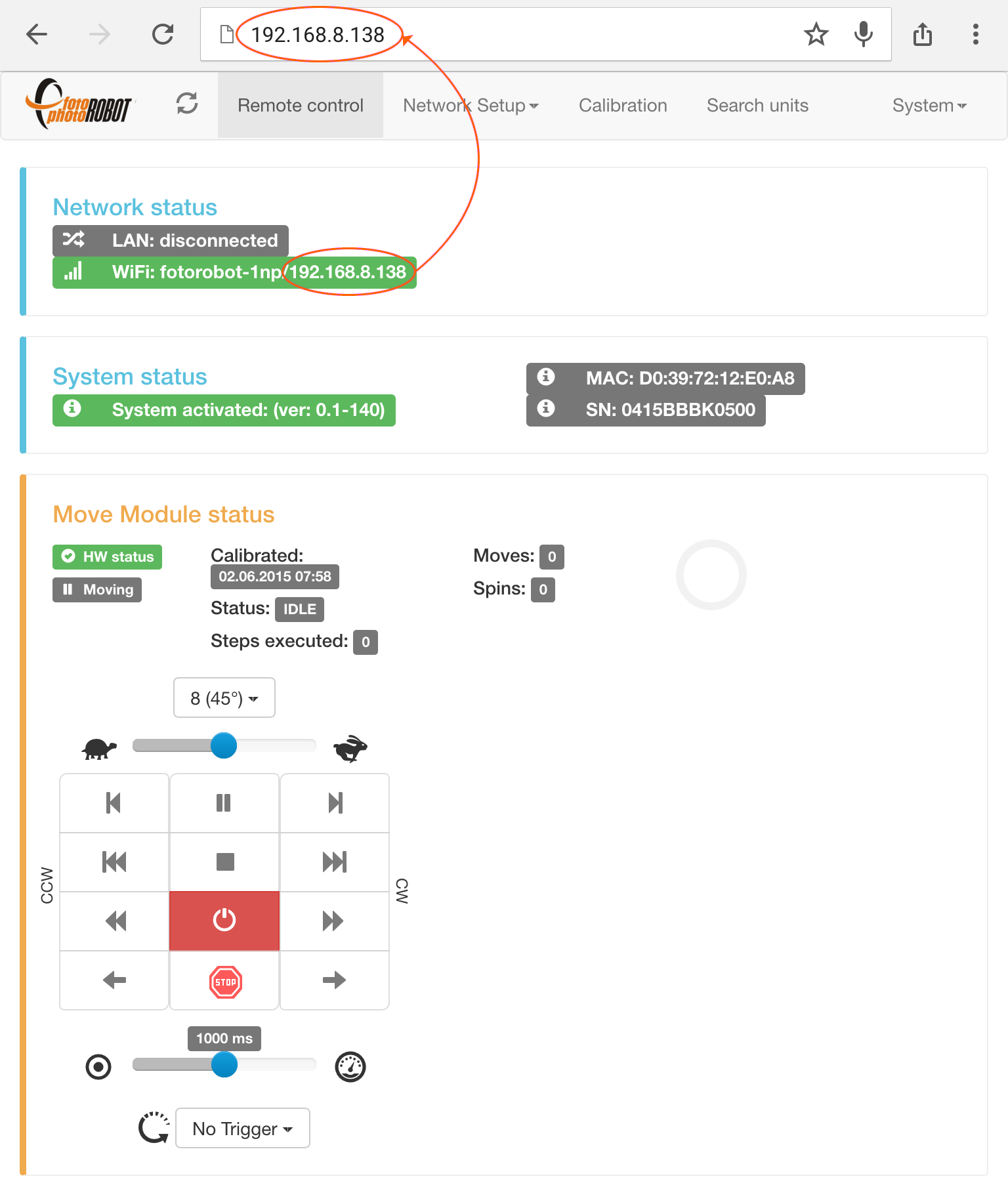
- Sekarang, CASE terhubung ke jaringan nirkabel yang Anda pilih dan Anda dapat mengaksesnya melalui alamat IP-nya yang ditampilkan di bidang status Jaringan.
4.3.2. Aplikasi Kontrol PhotoRobot
Pada akhir 2015, PhotoRobot meluncurkan aplikasi pengontrolnya, PhotoRobot Controls. PhotoRobot Controls menyediakan kontrol atas robot, kamera, dan lampu kilat; mengedit foto secara real time selama urutan; menghasilkan teknik khusus seperti pemotongan otomatis; masking chromakey dan penumpukan DoF untuk kedalaman bidang yang ditingkatkan; dengan alur kerja, database, unggahan otomatis, dan banyak lagi.
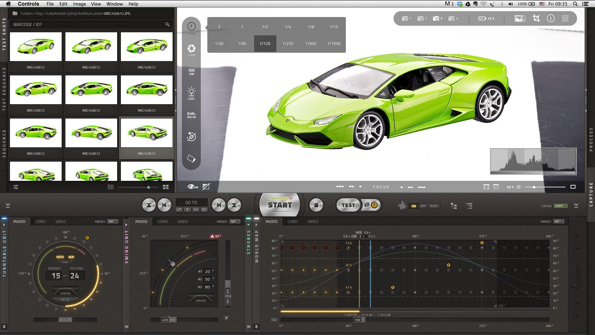
- Antarmuka pengguna aplikasi PhotoRobot Controls bersifat visual dan intuitif untuk digunakan.
4.4. Kalibrasi
Catatan: CASE 850 generasi terbaru tidak lagi menggunakan cangkir hisap magnetik. Sebagai gantinya, sensor optik tersembunyi membaca rotasi 360° penuh dari bevel mekanis yang digiling ke tepi pelat kaca. Kalibrasi bekerja persis sama — tidak ada cangkir hisap yang perlu dipasang, jadi Anda bisa melewati langkah-langkah cangkir hisap di bawah ini.
Kalibrasi penting untuk presisi dan kinerja optimal CASE, dan harus diselesaikan setelah setiap instalasi CASE. Selanjutnya, kalibrasi disarankan sesuai dengan kondisi spesifik, volume foto yang diambil; penuaan X-ring, kebersihan piringan kaca, berat produk yang difoto, dll.
Untuk mengkalibrasi CASE, Anda harus menghubungkannya ke aplikasi Antarmuka Pengguna berbasis Browser (lihat bab 4.3.1 - Aplikasi Antarmuka Pengguna berbasis Web).
- Sebelum Anda memulai kalibrasi, pastikan CASE dihidupkan dan tidak ada daya ke motor sehingga Anda dapat memutar pelat kaca dengan bebas menggunakan tangan.
- Untuk kalibrasi, Anda memerlukan cangkir hisap magnetik yang disimpan di sisi dalam badan CASE-nya.
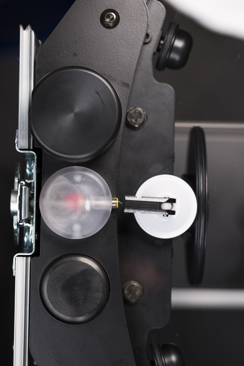
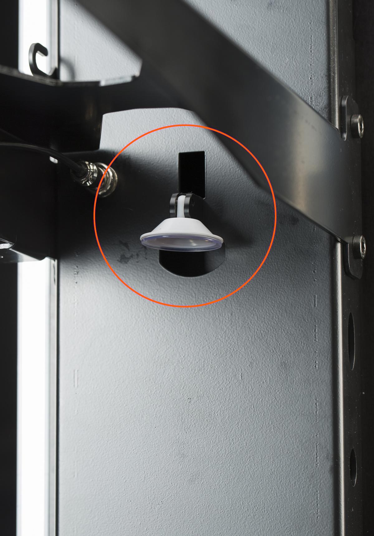
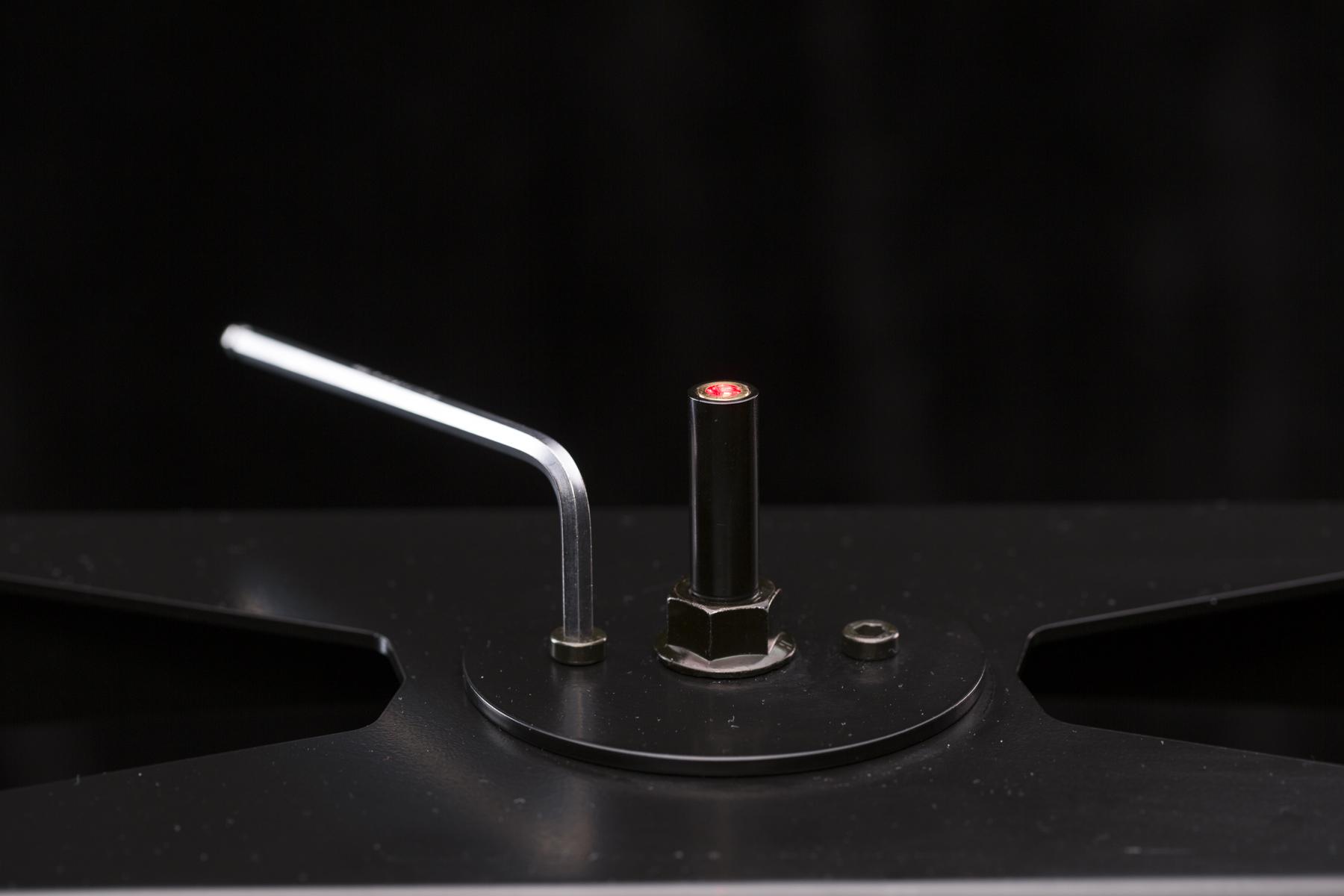
- Probe kalibrasi terletak di atas CASE di sebelah encoder. Letakkan cangkir hisap tertutup di dekat probe (sekitar 0,5 mm atau 0,02 inci). Penempatan yang benar ditunjukkan oleh lampu merah probe.
- Putar pelat kaca dengan cangkir hisap di samping probe. Buka dan tutup cangkir hisap – cangkir hisap harus menempel kuat pada pelat kaca.
- Saat Anda memutar pelat kaca, cangkir hisap akan bertemu dengan probe kalibrasi. Ini akan menyalakan lampu merah untuk menunjukkan penempatan yang tepat dari kedua bagian.
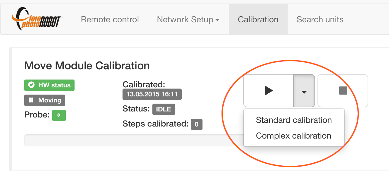
- Dalam aplikasi Antarmuka Pengguna berbasis Browser, buka Menu Kalibrasi. Pilih kalibrasi Standar (cepat dan cukup) atau Kompleks (lebih lama dan lebih presisi), tekan tombol putar, dan urutan kalibrasi otomatis akan dimulai.
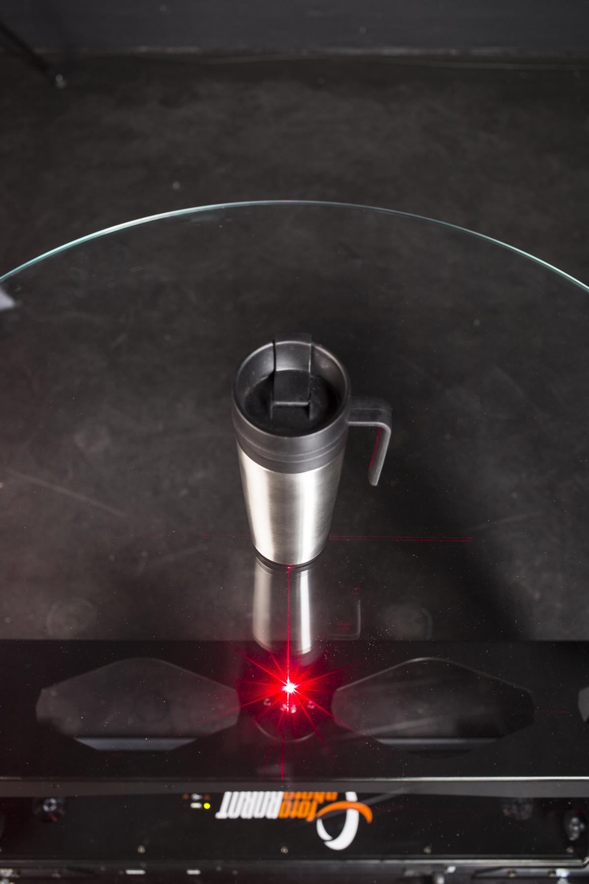
4.5. Laser Pemusatan (Uji Titik)
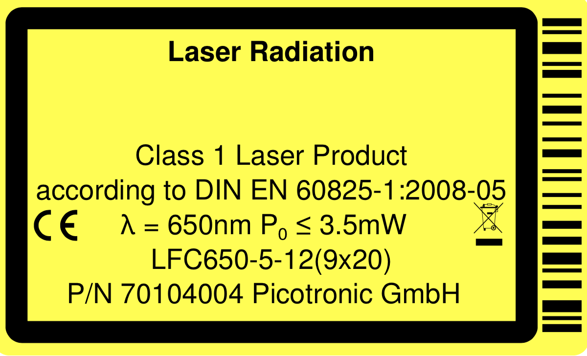
PERHATIAN: Laser Kelas 1 (λ = 650nm P0 ≤ 3.5mW) digunakan - hindari paparan mata langsung (jangan melihat ke dalam berkas cahaya) - dan sebagai tambahan - secara opsional - gunakan Kacamata atau Gogel pelindung.
Agar dapat menempatkan setiap produk yang difoto secara akurat di atas piringan kaca, sangat penting untuk memusatkan laser silang terintegrasi dengan tepat. Untungnya, ada teknik yang mudah dan menyenangkan untuk melakukannya, dijelaskan di bawah ini.
Catatan: CASE 850 memiliki laser silang bawaan. Untuk proyeksi dari atas atau dari sudut nyaman lainnya, laser tambahan opsional tersedia sebagai aksesori. Sistem menggerakkannya secara otomatis — mereka menyala setelah setiap urutan foto sehingga produk berikutnya dapat ditempatkan segera, dan mati selama pengambilan gambar sehingga laser tidak pernah muncul dalam foto. Laser tambahan paling cocok untuk instalasi studio permanen, sementara untuk pekerjaan di lokasi yang mobile, laser bawaan saja biasanya lebih disukai.
- Tempelkan selotip ke perkiraan tengah pelat kaca dan jalankan urutan dengan beberapa pemberhentian (enam dalam contoh ini).
- Tandai persilangan laser di setiap pemberhentian dengan pena.
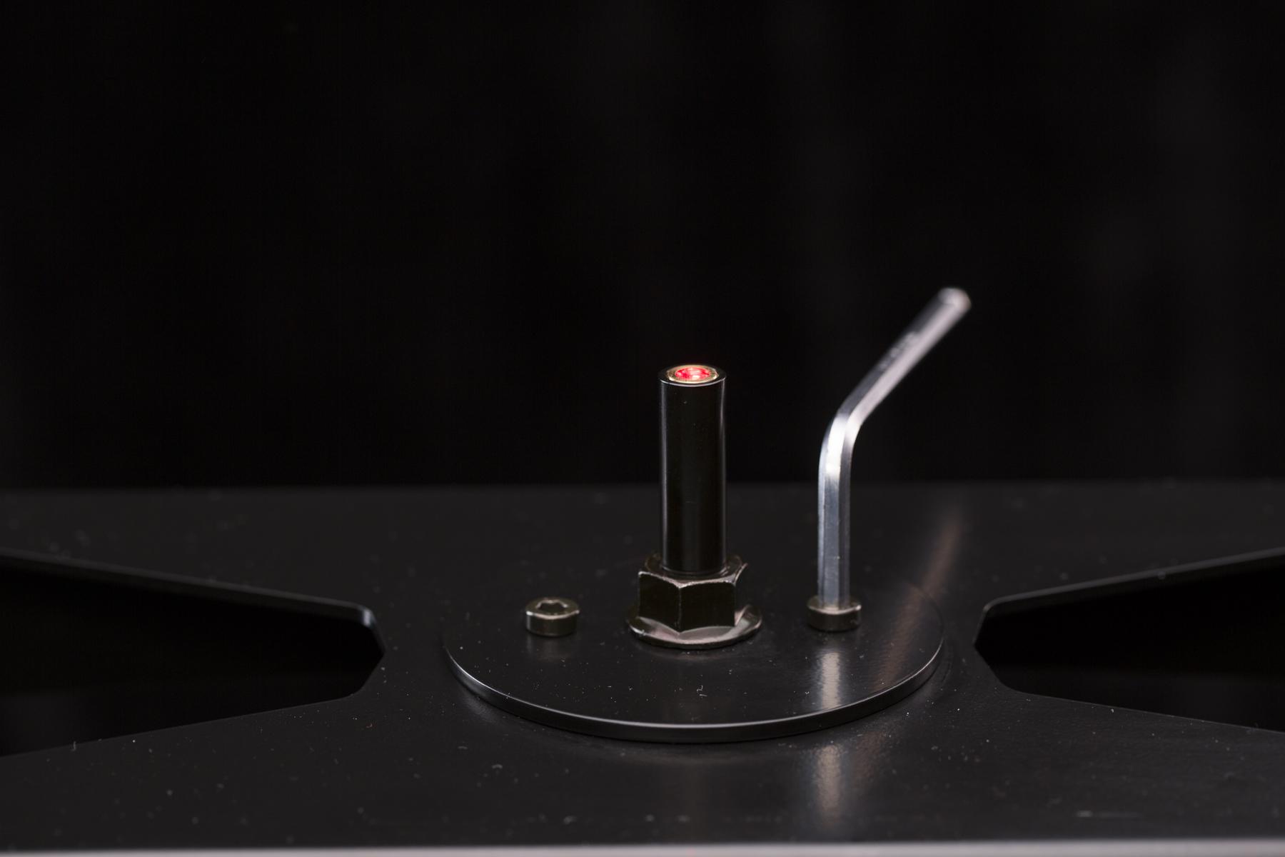
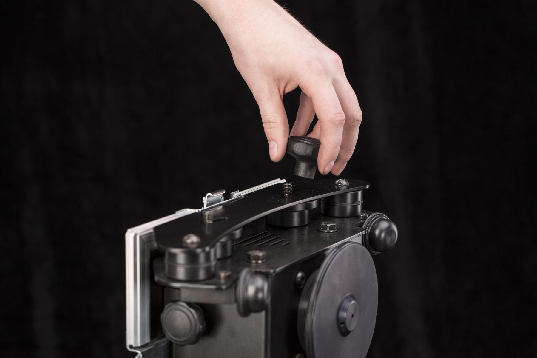
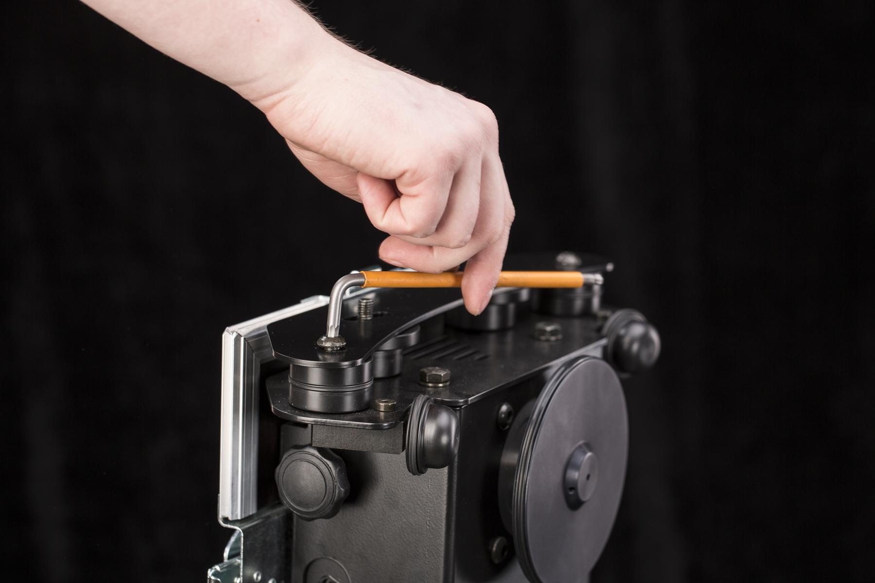
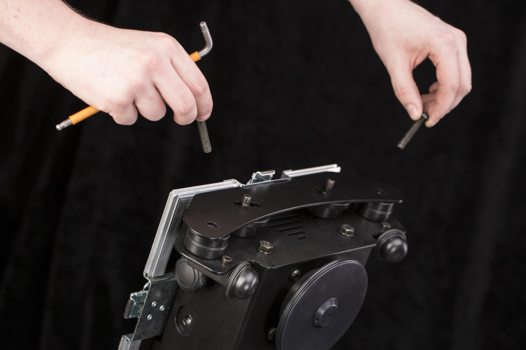
- Kendurkan sekrup laser dengan kunci hex agar laser dapat bergerak bebas.
- Ketika seperti yang ditunjukkan di atas, laser sekarang dapat bergerak ke kiri - kanan, dan maju - mundur.
- Tandai persilangan laser pada setiap pemberhentian urutan menggunakan instruksi di atas.
- Hubungkan tanda yang berlawanan – ini menciptakan pusat / sumbu yang tepat dari pelat kaca.
- Pindahkan silang laser ke tengah pelat kaca dan kencangkan sekrup laser.
4.6. Letakkan Produk
Penting untuk menempatkan sumbu SPIN produk di tengah pelat kaca. Pusat rotasi yang tepat (ECR) dari pelat kaca digambarkan oleh laser silang terintegrasi (pengaturannya dijelaskan dalam bab sebelumnya). Namun, untuk menentukan sumbu SPIN produk, mungkin agak rumit. Biasanya, itu adalah pusat geometris, tetapi ada pengecualian; misalnya, wajan bergagang panjang harus memiliki sumbu SPIN di pusat geometris wajan, sementara gagang panjang harus berputar di sekitarnya.
- Dengan proyeksi laser silang dari bawah, biasanya lebih mudah untuk menentukan sumbu produk dari bawah.
PERHATIAN: Tidak diperbolehkan meletakkan benda tajam di atas pelat kaca yang dikeraskan! Ini dapat menggores atau memecahkan kaca. Kapasitas berat atau meja mungkin terbatas jika berat tidak didistribusikan secara merata atau hanya terfokus pada beberapa titik. Untuk meletakkan benda tajam di atas meja, disarankan untuk menggunakan kaca akrilik transparan sebagai lapisan pemisah ke permukaan meja kaca.
4.7. Atur Kamera
4.7.1. Tempatkan Kamera
Penempatan kamera yang benar sangat penting saat memotret foto 360 derajat; produk harus berputar dengan mulus di tengah FRAME.
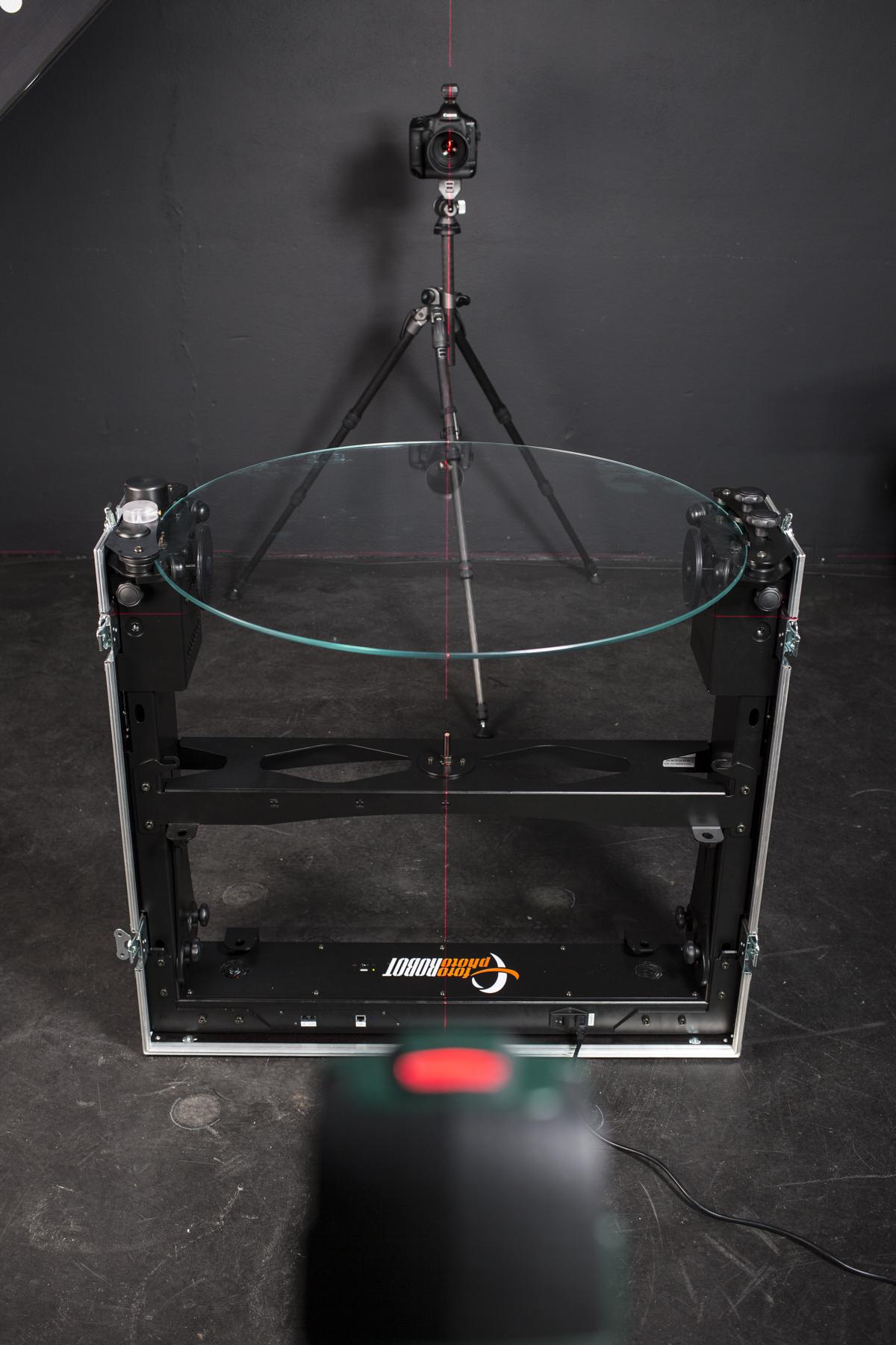
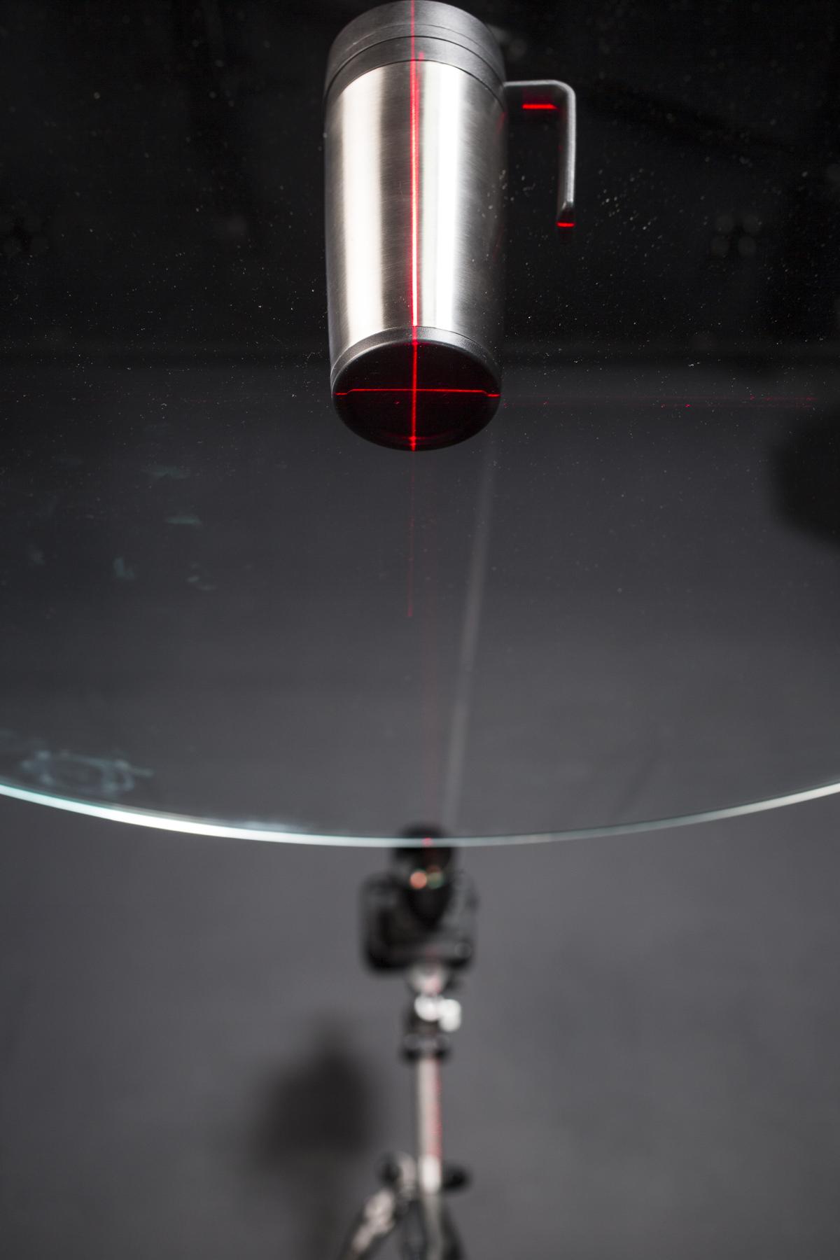
- Gunakan laser perata otomatis untuk menyelaraskan kamera dan CASE secara tepat. Proyeksikan laser perata otomatis sejajar dengan laser silang terintegrasi dan tempatkan kamera sehingga laser melewati bagian tengah lensa.
4.7.2. Sambungkan Kamera
Jika Anda menggunakan aplikasi desktop PhotoRobot (PhotoRobot Controls) untuk mengoperasikan CASE, Anda juga dapat menggunakannya untuk mengontrol kamera. Atau, Anda cukup menyinkronkan kamera dengan robot menggunakan pemicu nirkabel atau kabel yang dicolokkan langsung ke CASE.
4.7.3. Pengaturan Kamera
Tentu saja, perlu untuk mengatur fokus, eksposur, dan kualitas gambar kamera. Untuk melakukan ini, kami merekomendasikan hal berikut.
- Gunakan JPEG untuk produksi standar – pemrosesan dalam kamera dari bodi Canon (atau iPhone) menghasilkan hasil yang sangat baik dan siap pakai; RAW tetap menjadi pilihan bagi para penggemar yang ingin menyempurnakan rentang dinamis maksimum, misalnya untuk cahaya latar yang kuat dari latar belakang putih murni.
- Gunakan ISO rendah – Anda akan mendapatkan rentang dinamis dan kualitas gambar tertinggi dari sensor Anda.
- Gunakan LiveView – ini adalah cara terbaik untuk memfokuskan dan menyelaraskan subjek Anda dengan benar.
- Uji lensa Anda – deteksi kinerja optimal lensa Anda; Anda mencari nilai apertur tertinggi dengan ketajaman dan transmisi kontras yang dapat diterima – sebagian besar lensa menurunkan kualitas gambar pada sekitar f/16.
4.8. Atur Cahaya
Mengatur cahaya dengan benar adalah tugas yang paling sulit dari semua tugas saat memotret foto 360 derajat. Kami merekomendasikan penggunaan strobo, karena memungkinkan lebih banyak kebebasan dalam hal pemodelan cahaya, dan juga menghemat waktu Anda dengan memungkinkan kecepatan rana yang lebih cepat.
4.8.1. Tempatkan Lampu
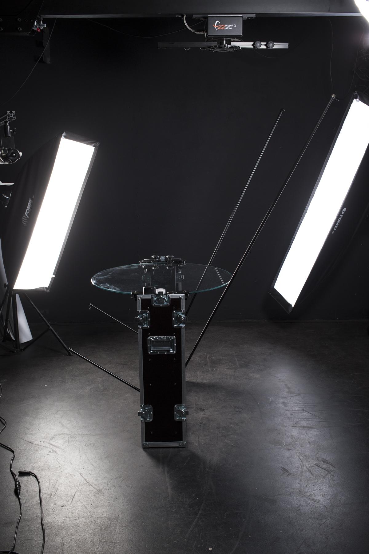
Sangat penting untuk menerangi latar belakang secara merata untuk mendapatkan latar belakang putih bersih tanpa memerlukan pasca-pemrosesan. Anda akan membutuhkan satu atau dua lampu untuk melakukannya, tergantung pada ukuran produk (produk kecil tidak memerlukan ruang yang diterangi secara merata sebanyak produk besar).
- Tampilan Atas diilustrasikan di atas – dengan satu atau dua lampu strobo di belakang, dan dua lampu strobo di depan / samping.
- Tampilan Samping diilustrasikan di atas – dengan penempatan lampu kilat belakang.
- Ini adalah Tampilan Belakang ke Depan – dengan dua lampu strobo di depan / samping.
Sisa pencahayaan terbuka untuk interpretasi kreatif Anda. Perlu diingat, pencahayaan untuk fotografi 360 derajat sangat berbeda dengan pencahayaan untuk satu bidikan STILL; produk memantulkan pencahayaan secara bervariasi pada setiap sudut, mis. 36 sudut. Ini biasanya mendiskualifikasi penggunaan pencahayaan keras apa pun.
4.8.2. Sambungkan Lampu
Jika Anda menggunakan aplikasi desktop PhotoRobot (PhotoRobot Controls) untuk mengoperasikan CASE, Anda dapat menggunakannya untuk mengontrol semua pengaturan lampu kilat (FOMEI / RiME LITE, Broncolor, Profoto, dan lainnya termasuk produsen dengan dukungan yang akan datang dalam waktu dekat) dengan nyaman. Sinkronisasi rana kamera ke lampu kilat selama urutan SPIN perlu dilakukan dengan kabel sinkronisasi standar atau pemicu jarak jauh.
4.8.3. Pengaturan Lampu
Intensitas pencahayaan perlu diatur agar sesuai dengan nilai apertur yang ditentukan (untuk mendapatkan kedalaman bidang dan kualitas optik yang optimal). Untuk melakukan ini, gunakan tips berikut.
- Gunakan lampu kilat yang cukup kuat – sekitar 700 Ws berfungsi dengan baik saat ini; untuk penerangan yang paling merata baik pada produk maupun latar belakang, kami merekomendasikan penggunaan beberapa lampu untuk mencapai kontrol yang lebih baik atas pencahayaan. Daya yang memadai juga memperpendek waktu daur ulang dan memperpanjang masa pakai lampu kilat.
- Gunakan beauty dish dan strip softbox – mereka memberikan cahaya pemodelan yang lembut namun efisien; sempurna untuk fotografi 360 derajat.
- Dekatkan ke produk – membiarkan lampu strobo jauh dari produk menurunkan kualitas cahaya.
- Hindari pencahayaan datar – sangat jarang menonjolkan produk, dan tidak menggambarkan material produk dengan benar.
4.9. Jalankan Urutan
Pertimbangkan hal berikut saat mengatur urutan:
- Jumlah langkah – semakin banyak gambar dalam satu SPIN, semakin mulus transisi antar bingkai pengalaman 360 derajat, tetapi juga waktu produksi yang lebih lama dan volume data yang lebih besar. 24 - 36 bidikan per SPIN optimal dalam kebanyakan kasus (baca lebih lanjut di Fotografi Produk 360 - Format Konten dan Produksi).
- Akselerasi dan kecepatan – kecepatan harus sesuai dengan karakteristik produk yang difoto, misalnya, gerakan lambat untuk menghindari goyangan produk yang ditopang oleh senar pancing.
- Penundaan sebelum / setelah pengambilan gambar – penundaan terkadang diperlukan untuk menstabilkan produk yang berayun atau untuk memberi waktu pada lampu kilat untuk mengisi daya sepenuhnya.
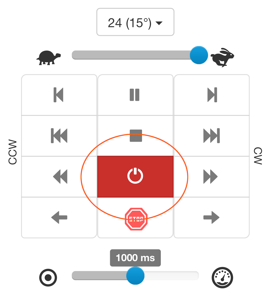
Ilustrasi berikut menggunakan Aplikasi Antarmuka Pengguna berbasis Browser untuk menjalankan urutan. Untuk petunjuk tentang cara menghubungkan CASE ke aplikasi ini, silakan lihat bab 4.3.1 - Aplikasi Antarmuka Pengguna berbasis Web.
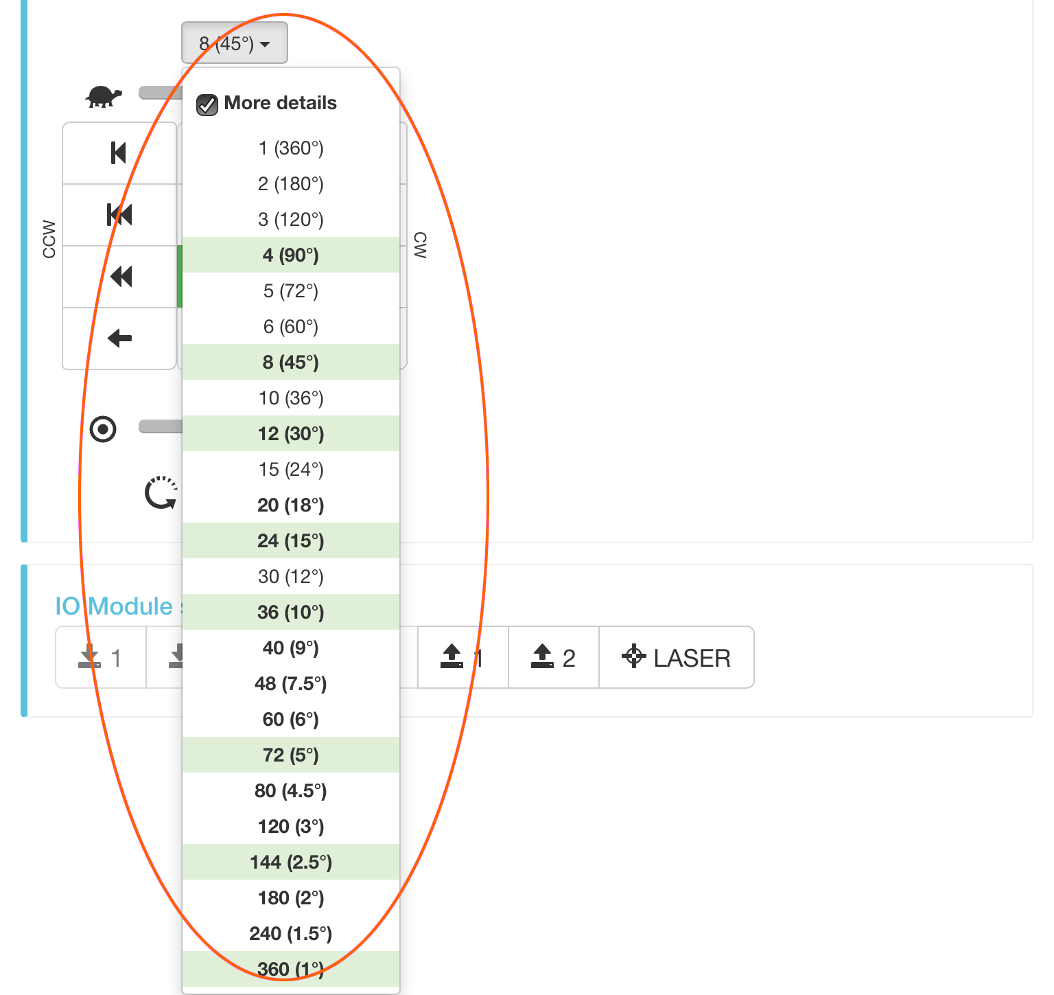
- Anda dapat memilih dari berbagai urutan prasetel.
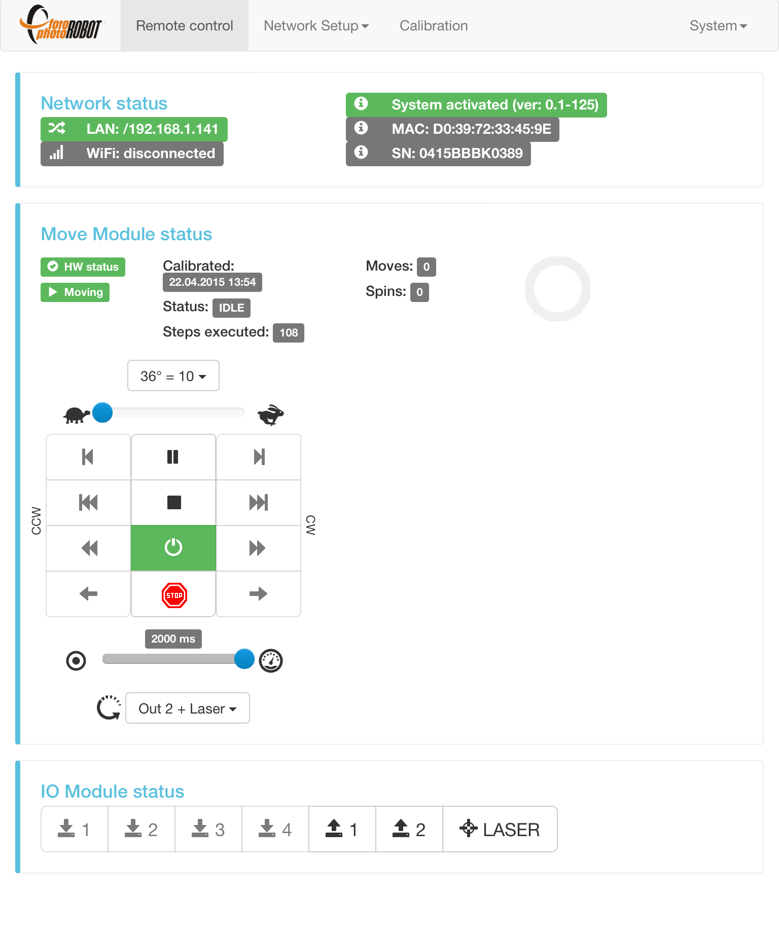
- CASE dioperasikan oleh pengontrol yang dilingkari.
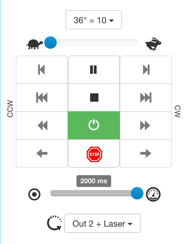
- Urutan prasetel
- Kecepatan rotasi Min / Maks
- Satu langkah berlawanan arah jarum jam (CCW) / satu langkah searah jarum jam (CW)
- Mode langkah 360° CCW / CW
- Mode langkah CCW / CW berkelanjutan
- Rotasi CCW / CW berkelanjutan (tanpa langkah)
- Jeda rotasi / urutan (akan mencapai pemberhentian terdekat)
- Hentikan rotasi / urutan (akan segera melambat dan berhenti, tetapi tidak mencapai pemberhentian terdekat)
- Nyalakan / Nonaktifkan motor
- Penghentian darurat segera (tanpa ramp perlambatan)
- Penundaan antara penghentian urutan (pemicu kamera ditekan dalam ½ dari interval yang dipilih)
- Urutan prasetel (pemicu kamera ditekan di setiap pemberhentian, laser menyala saat urutan tidak berjalan)
5. Membuat Output
CASE 850 dioperasikan oleh PhotoRobot Controls, paket perangkat lunak kami sendiri yang menggerakkan kamera, lampu, dan robot dalam satu alur kerja. Dalam kebanyakan kasus, PhotoRobot Controls menghasilkan output siap web secara langsung — gambar statis, fotografi SPIN 360° deep-zoom, video, dan model 3D — tanpa memerlukan perangkat lunak pihak ketiga.
Jika Anda lebih suka alur kerja Anda sendiri, gambar yang diambil dengan CASE 850 dapat diekspor dan diproses dalam alat pihak ketiga pilihan Anda. Sebagai alternatif, lisensi API tersedia untuk kontrol langsung perangkat keras CASE 850, memungkinkan Anda membangun perangkat lunak kustom yang melakukan tugas yang sama dengan PhotoRobot Controls.
6. Pemeliharaan
Untuk menjaga kinerja optimal CASE 850, tidak banyak yang perlu dilakukan. Lihat bab-bab berikut yang menjelaskan perawatan yang baik untuk perangkat Anda.
6.1. Pembersihan
Disarankan untuk menjaga CASE tetap di lingkungan yang bersih, dan membersihkannya secara teratur untuk mencegah polusi pada elektronik yang terletak di dasar CASE.
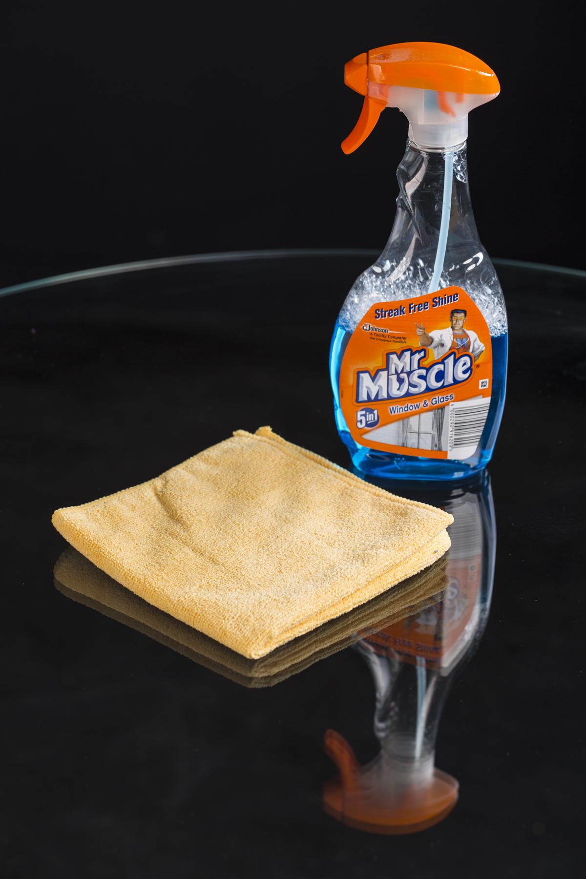
Catatan: Pemolesan kaca secara teratur sangat penting. Pembersih layar atau jendela apa pun akan berfungsi untuk ini. Pastikan untuk menggunakan handuk atau lap yang tidak meninggalkan serat, serabut, bulu halus, atau partikel kecil lainnya.
6.2. Mengganti X-ring
X-rings digunakan untuk memberikan cengkeraman pada roda yang menggerakkan pelat kaca atau menjaganya tetap pada posisi yang benar. Namun, kadang-kadang, X-rings bisa aus. Ini bukan hal yang perlu dikhawatirkan. Anda dapat membeli X-rings cadangan dari PhotoRobot, atau di toko perangkat keras lokal Anda. Kemudian, mengganti X-rings tidaklah sulit. Lihat petunjuk di bawah ini.
Ukuran X-ring berikut digunakan di CASE:
- NBR70 107.32 mm × 5.33 mm (2 buah digunakan untuk roda motor stepper)
- NBR70 29,75 mm × 3,53 mm (4 buah digunakan untuk roda penopang bawah)
- NBR70 33 mm × 2,62 mm (4 buah digunakan untuk roda penyangga samping)
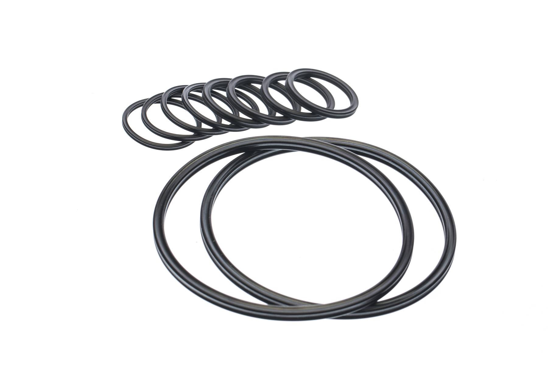
- Tiga ukuran cincin-X cadangan yang digunakan dengan CASE ditunjukkan di atas.
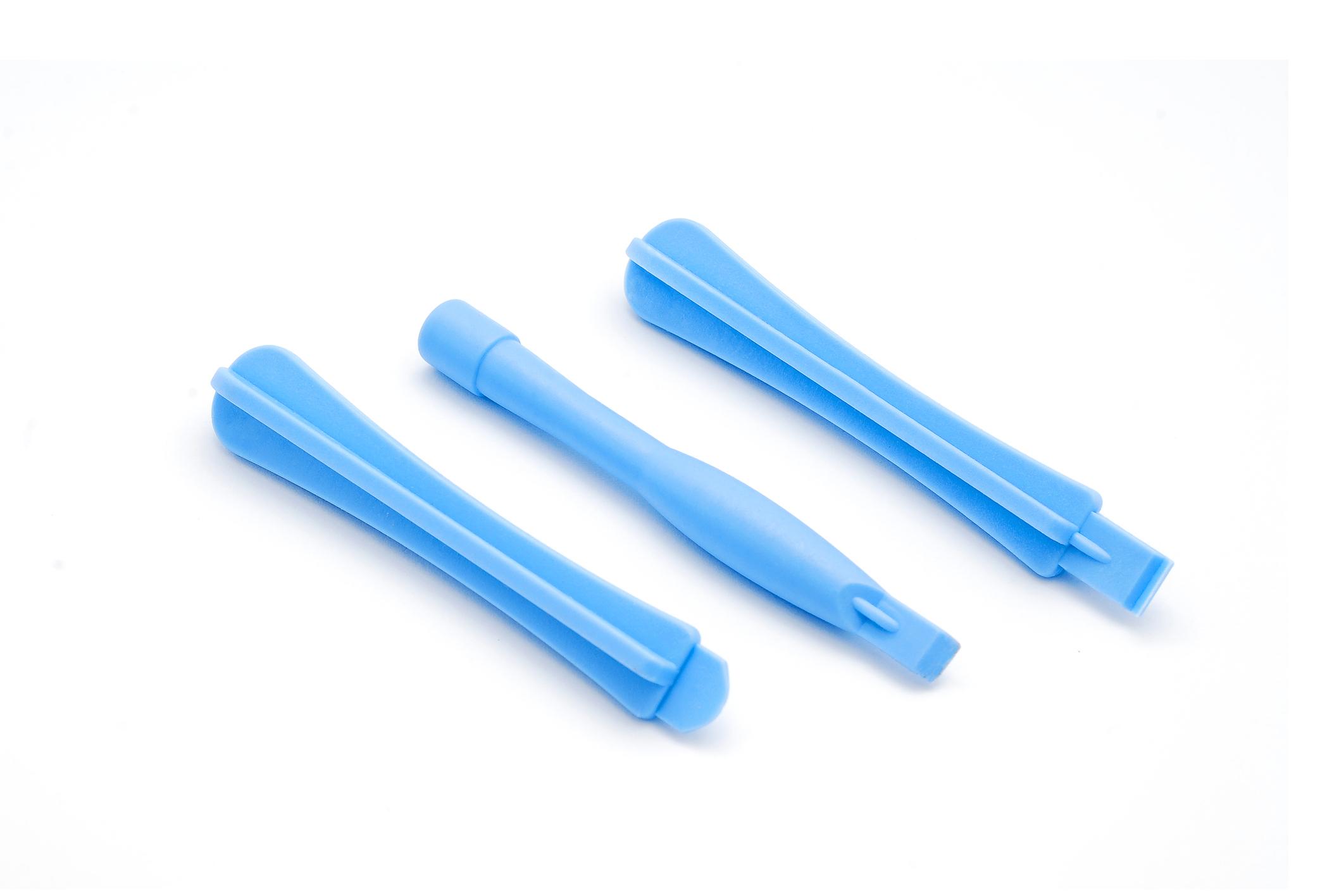
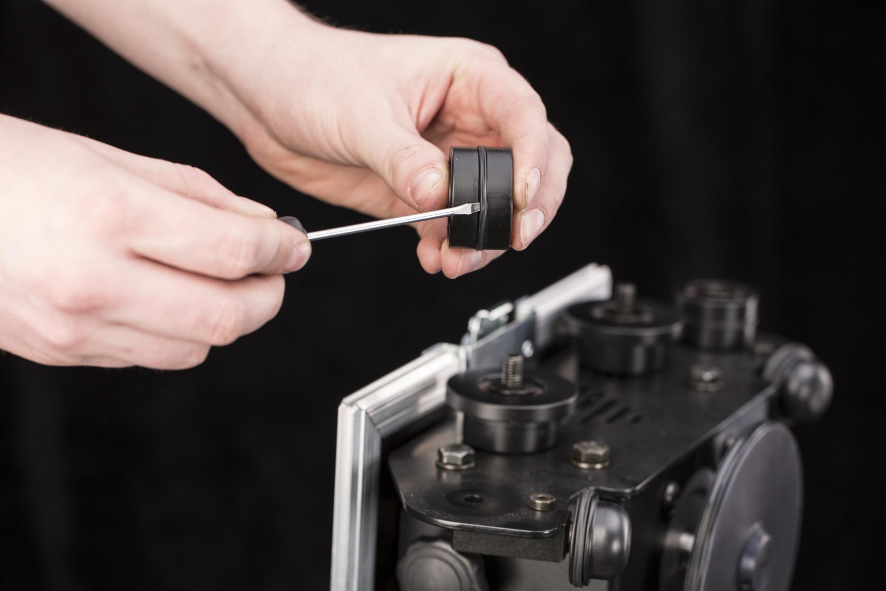
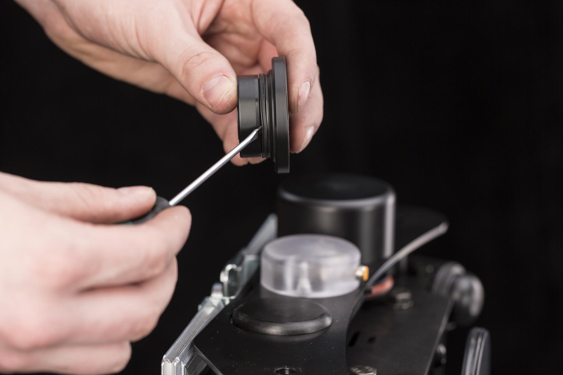
- Disarankan untuk selembut mungkin saat mengganti X-ring. Untuk menghindari risiko merobek X-ring yang STILL dapat digunakan atau merusak roda CASE mana pun, disarankan untuk menggunakan alat cungkil plastik (alat pembuka) – seperti yang digambarkan di atas. Namun, dengan kehati-hatian ekstra, Anda dapat menggunakan obeng pipih biasa, seperti yang ditunjukkan oleh teknisi berpengalaman kami dalam foto-foto di bawah ini.
6.2.1. Roda motor stepper
- X-ring besar pas dengan roda motor stepper yang menggerakkan pelat kaca.
- Gunakan obeng pipih untuk melepas X-ring.
- Untuk memasang X-ring, masukkan ke alur roda dan tarik melewati tepinya.
- Pastikan X-ring tidak terpelintir.
- Ketika X-ring terpasang dengan benar, remaslah agar tegangan X-ring sama di seluruh keliling roda.
6.2.2. Roda penyangga bawah
- X-ring pada roda penyangga bawah dapat diganti tanpa melepas roda.
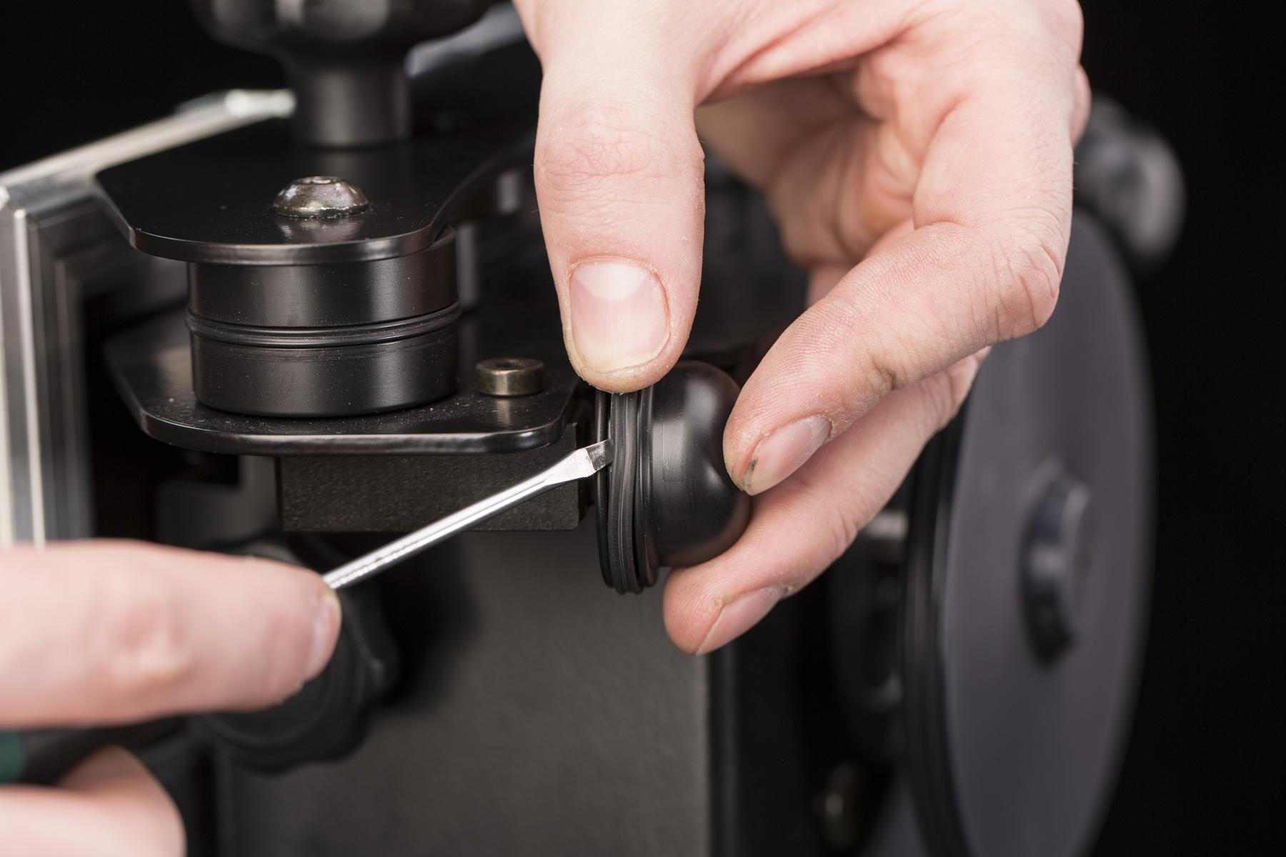
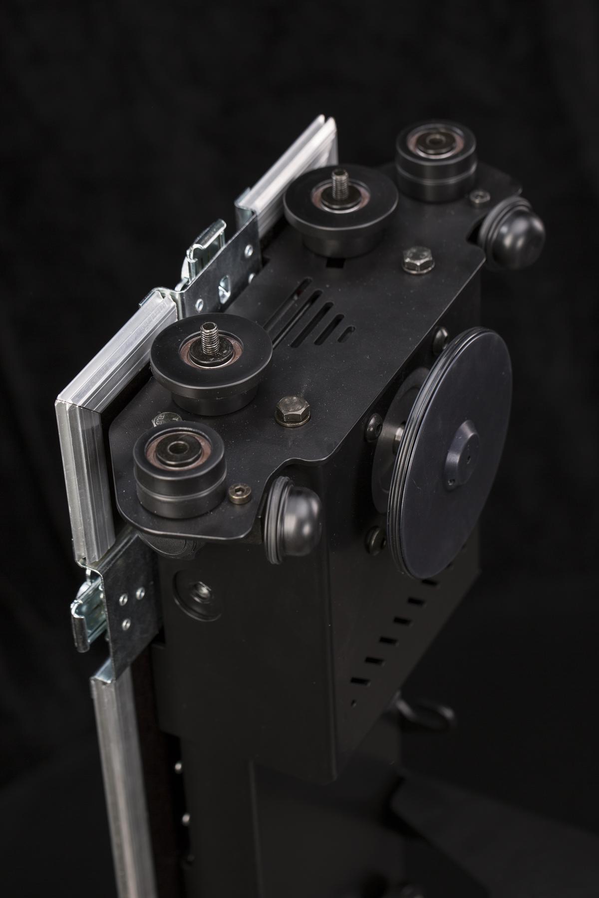
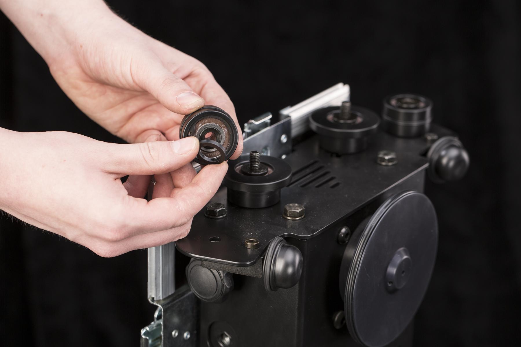
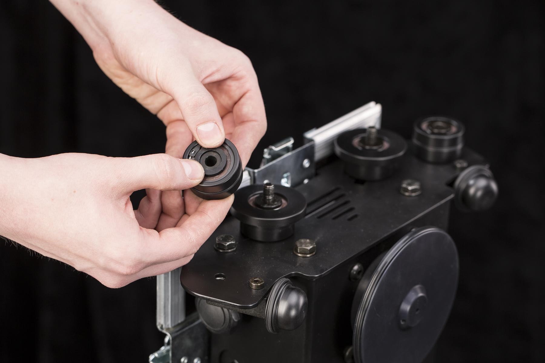
6.2.3. Roda penyangga samping
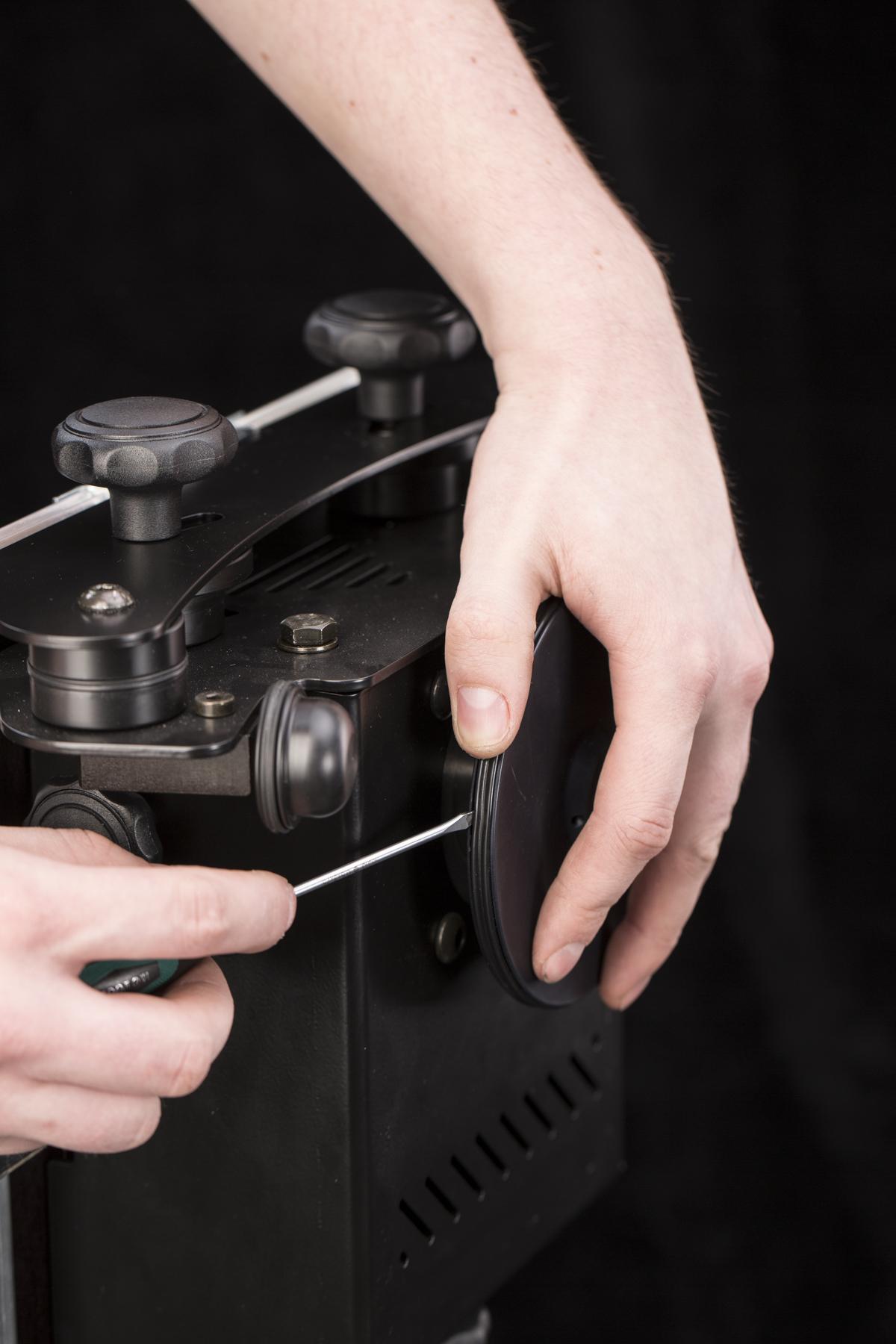
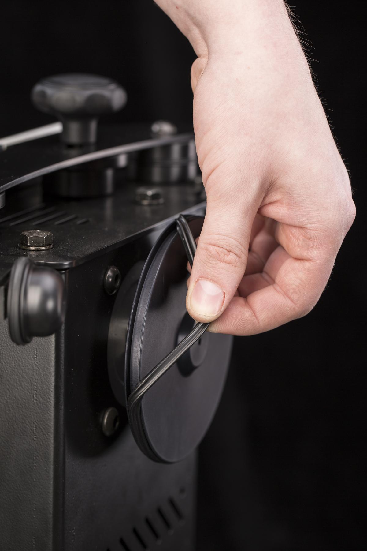
- Untuk mengganti X-ring pada roda penyangga samping, Anda perlu melepas penutupnya.
- Untuk melepas penutup, ada dua pegangan pengunci mur plastik yang harus dilepas.
- Lepaskan sekrup hex yang melewati roda penyangga.
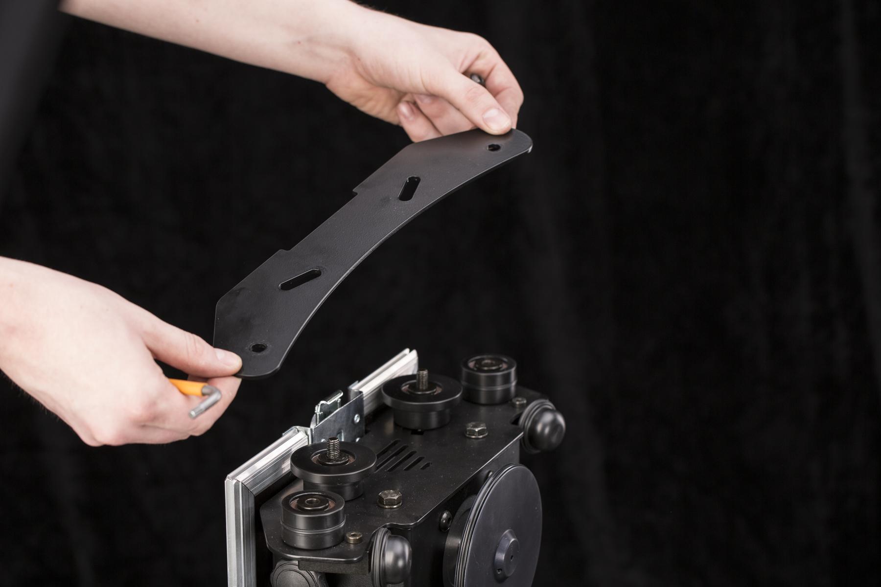
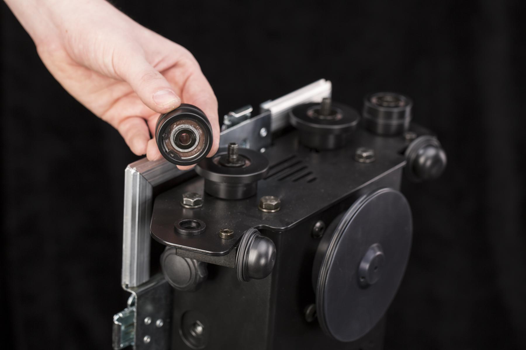
- Lepaskan penutup roda penyangga.
- Roda penyangga kini dapat dilepas sepenuhnya.
- Sekarang, X-ring dapat dengan mudah diganti.
- Saat Anda mengeluarkan roda penyangga, ring penjarak dapat dibiarkan di alas. Berhati-hatilah agar tidak menjatuhkan dan kehilangannya.
- Tekan kembali ring penjarak ke bagian bawah roda penyangga dan pasang kembali ke alas.
- Untuk mengganti X-ring roda penyangga di sisi dengan encoder, jangan lepaskan penutupnya. Cukup lepaskan sekrup hex.
- Ganti X-ring dengan cara yang sama seperti pada roda sebelumnya.
6.3 Pembaruan Firmware
Untuk memperbarui firmware CASE, perlu menghubungkan CASE ke internet dan antarmuka pengguna berbasis web. Prosesnya dijelaskan dalam bab 4.10.2 - Mengontrol CASE.
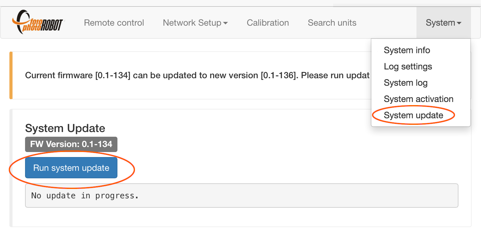
- Di menu, buka Sistem > Pembaruan sistem. Jika aplikasi menunjukkan versi firmware baru, tekan “Jalankan pembaruan sistem” untuk mendapatkan versi firmware terbaru.
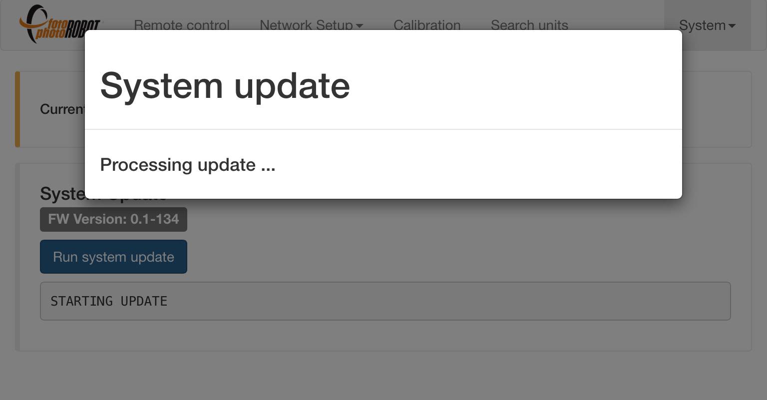
- Sisa pembaruan sepenuhnya otomatis.
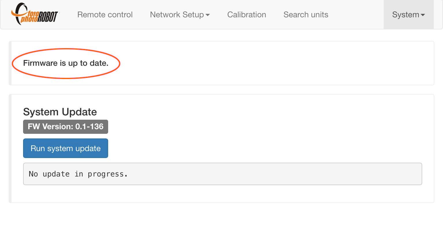
- Aplikasi menunjukkan firmware sudah mutakhir.
6.4. Aktivasi
Jika Anda mengalami kesalahan aktivasi, Anda dapat mencoba mengaktifkan kembali CASE Anda melalui aplikasi berbasis browser (untuk terhubung ke aplikasi lihat bab 4.3.1). Pastikan CASE terhubung ke jaringan internet. Jika reaktivasi gagal, silakan hubungi dealer CASE Anda untuk bantuan lebih lanjut.
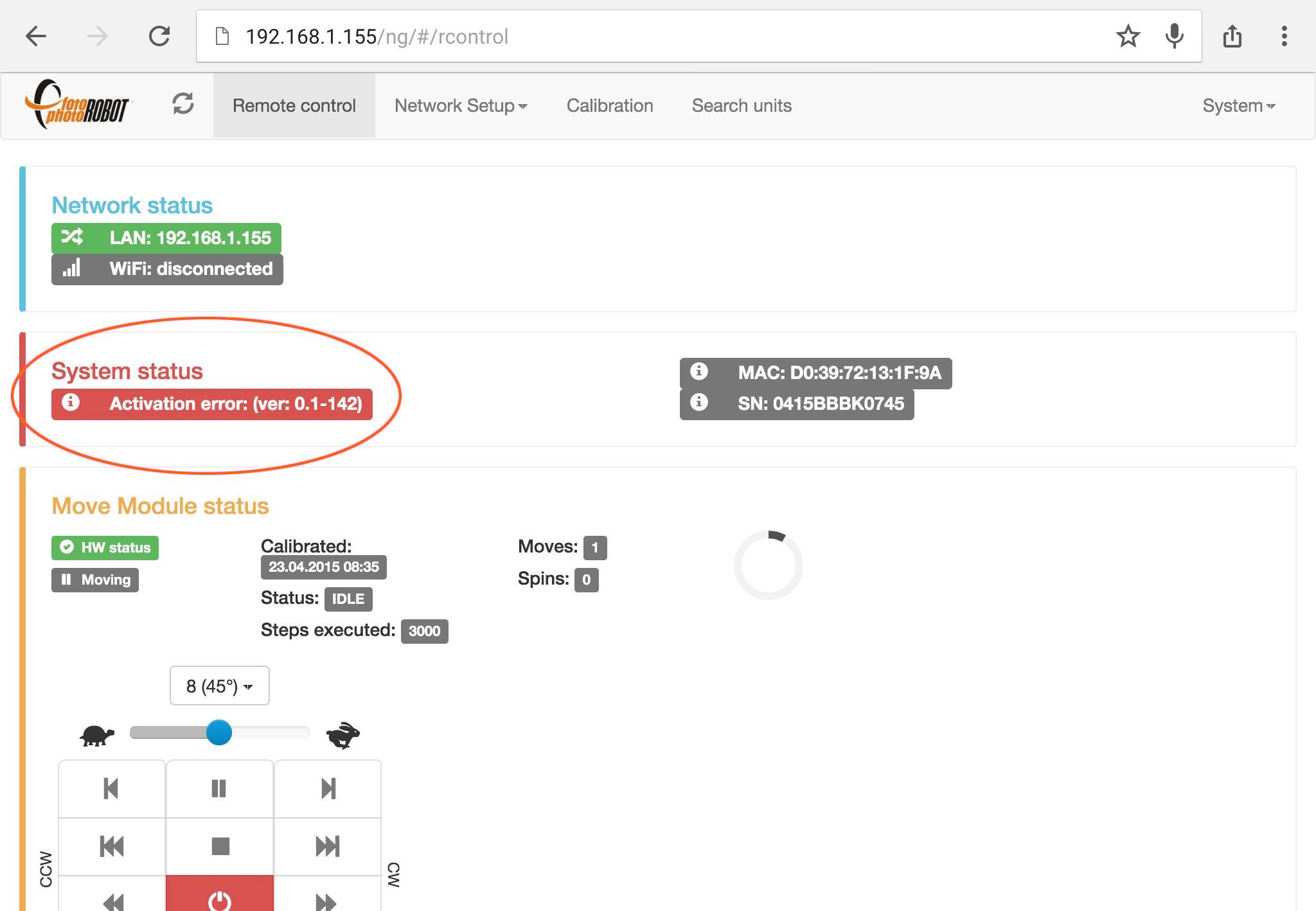
- Kesalahan aktivasi ditunjukkan di kotak status Sistem.
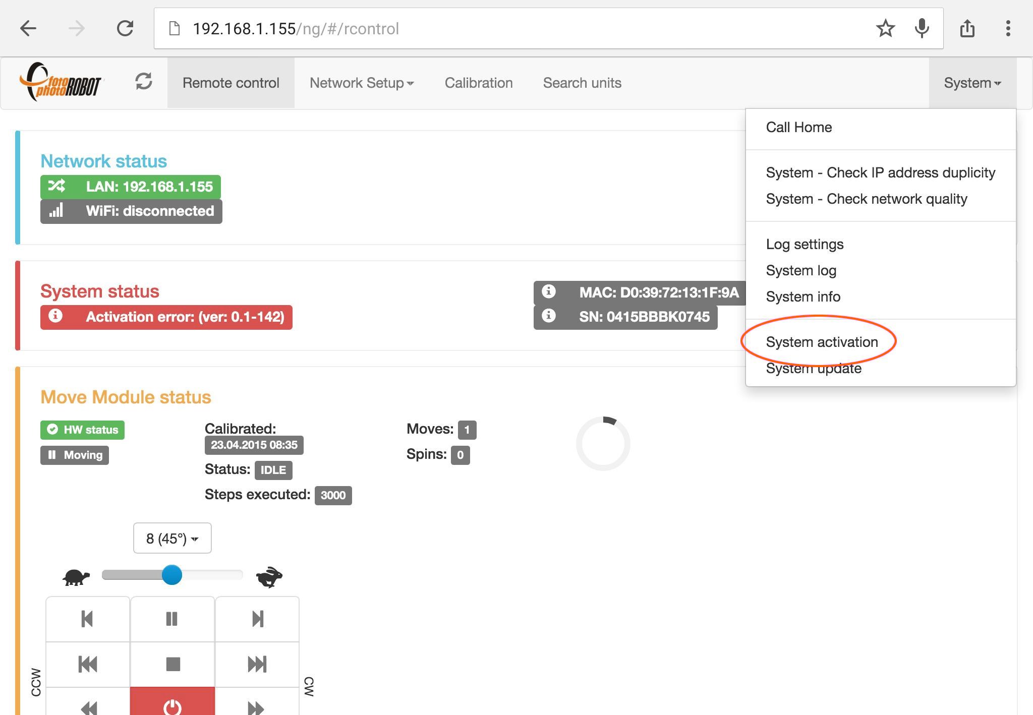
- Untuk mengaktifkan kembali CASE Anda, buka menu Sistem > Aktivasi sistem.
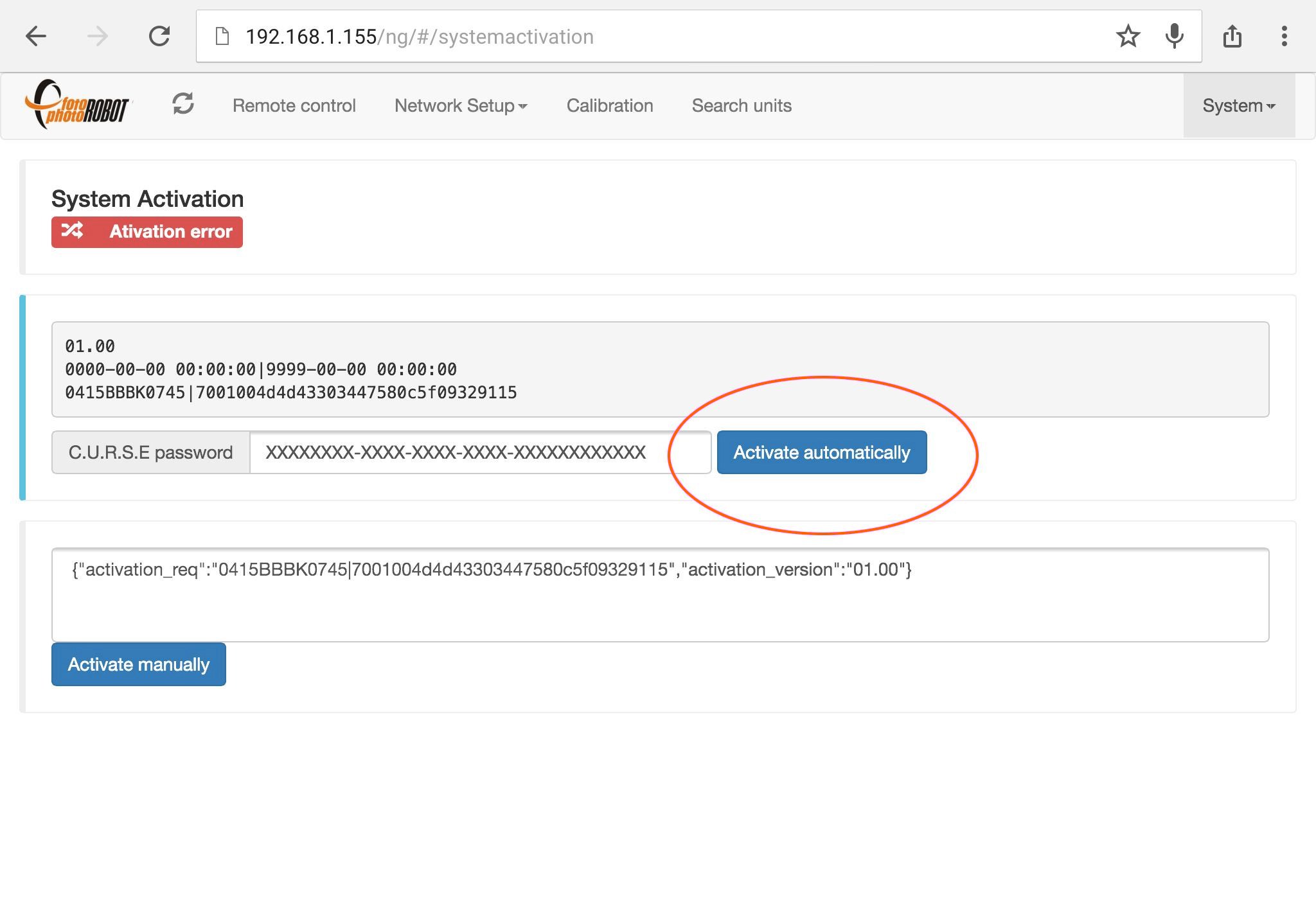
- Isi kata sandi aktivasi Anda dan tekan Aktifkan secara otomatis.
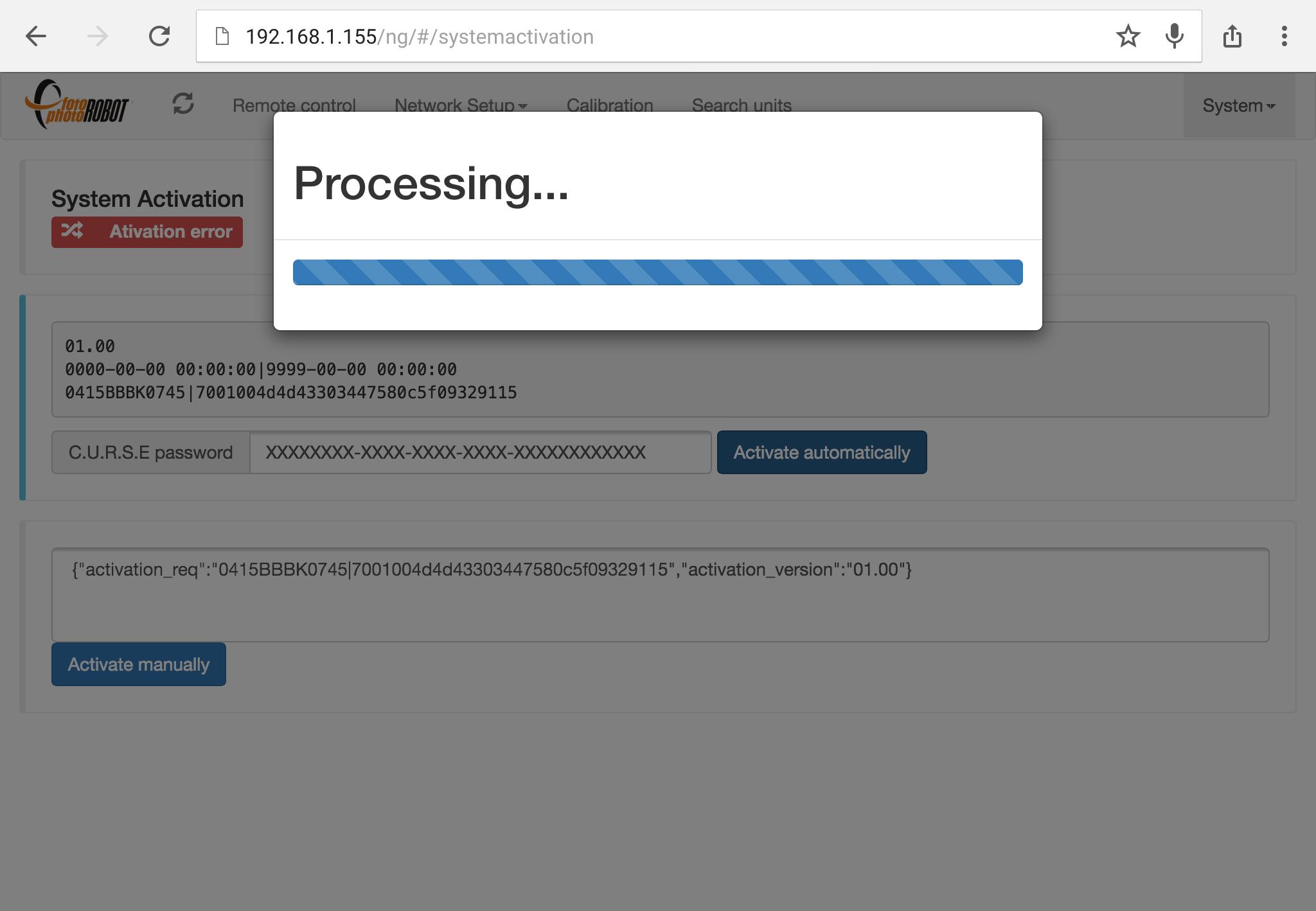
- Proses aktivasi memakan waktu sekitar dua puluh detik.
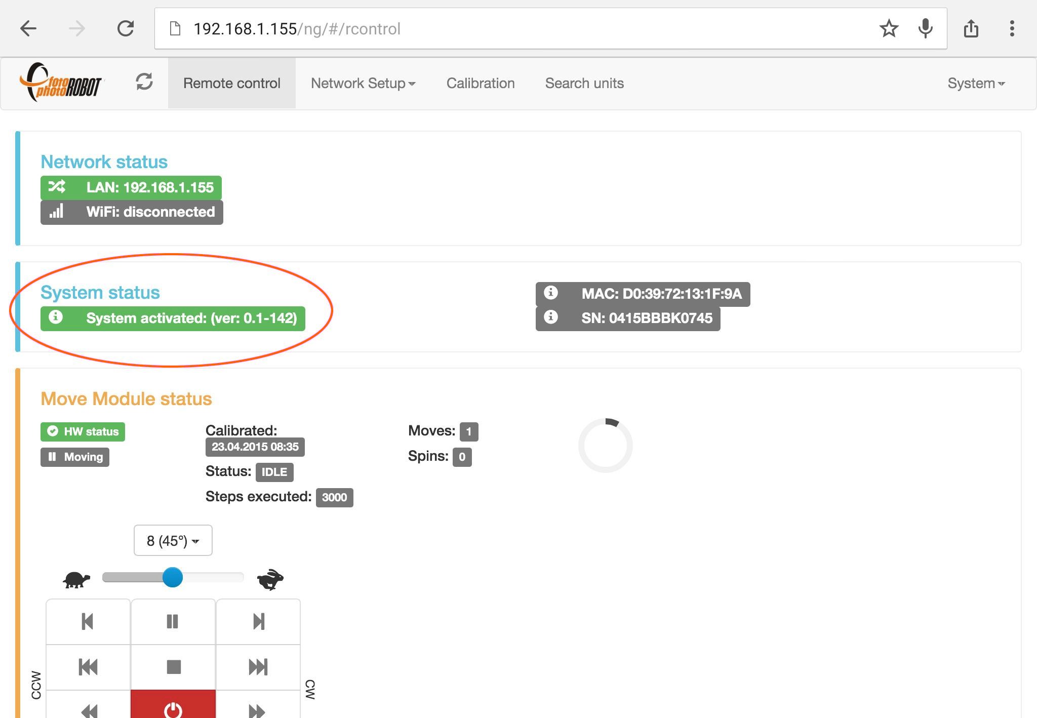
- Aktivasi berhasil ditunjukkan di kotak status Sistem.
7. Pertanyaan Umum
7.1. Apakah saya memerlukan peralatan atau aksesori apa pun untuk menjalankan CASE?
TIDAK, semua yang diperlukan untuk menjalankan CASE ada dalam paket. Anda hanya memerlukan kamera, satu set lampu, dan komputer untuk mengontrol CASE.
7.2. Apakah saya memerlukan komputer untuk mengontrol CASE?
YA, Anda memerlukan komputer yang menjalankan aplikasi PhotoRobot Controls untuk mengoperasikan CASE 850. Perangkat lunak ini mengontrol kamera, lampu, dan robot, sambil memproses gambar yang diambil segera menjadi keluaran siap publikasi — gambar statis, fotografi SPIN 360°, video, dan model 3D. Dengan lisensi API, opsi kontrol lebih lanjut dan aplikasi pihak ketiga juga tersedia.
Untuk spesifikasi komputer, lihat Persyaratan Sistem PhotoRobot.
7.3. Berapa lama waktu yang dibutuhkan untuk merakit CASE?
Untuk perakitan CASE 850, hanya butuh beberapa menit — sekitar 15 — untuk membuat CASE dari kondisi terkemas menjadi siap beraksi.
7.4. Bisakah saya menggunakan lampu kontinu dengan CASE?
YA, dimungkinkan untuk menggunakan lampu kontinu dengan CASE. Lampu kontinu LED modern sangat kuat dan berfungsi baik untuk banyak aplikasi – bahkan pemotretan produk yang lebih kecil tanpa henti pada kecepatan yang lebih rendah. Strobo tetap menjadi pilihan terbaik untuk produksi berkecepatan tinggi, tetapi pencahayaan kontinu adalah pilihan yang sangat baik untuk berbagai kasus penggunaan.
7.5. Bagaimana cara saya memicu kamera?
Untuk memicu kamera, dimungkinkan untuk melepaskan rana kamera menggunakan pemicu kabel atau nirkabel yang terhubung ke CASE, atau dengan USB yang terhubung ke komputer.
7.6. Bisakah saya mengoperasikan CASE tanpa koneksi internet?
YA, CASE dapat dioperasikan tanpa koneksi internet. Namun, Anda perlu menghubungkannya ke beberapa jaringan untuk mengaksesnya melalui aplikasi kontrol. Ini bisa berupa LAN, WLAN, atau jaringan yang disediakan oleh CASE itu sendiri (menggunakan modul Wi-Fi USB). CASE dapat berjalan sepenuhnya offline; namun, dalam praktiknya, seringkali lebih nyaman untuk menjaga beberapa konektivitas tetap tersedia — bahkan jika itu terbatas pada pertukaran metadata saja. Untuk opsi penerapan terperinci, lihat manual PhotoRobot Controls, atau hubungi penjualan atau dukungan teknis PhotoRobot untuk mendiskusikan pengaturan yang Anda inginkan, termasuk penerapan sepenuhnya offline dan tidak dapat dilacak untuk sistem lapangan di mana ketidakmampuan untuk melacak peralatan sangat penting untuk keselamatan operator.
7.7. Kamera apa yang bisa saya gunakan dengan CASE?
Untuk melihat kamera mana yang dapat Anda gunakan dengan CASE, kamera yang didukung dan terbaru tersedia secara online — lihat Kamera Kompatibel PhotoRobot dan Kamera yang Direkomendasikan PhotoRobot. Kami dapat menyediakan kabel atau pemicu nirkabel untuk model yang didukung.
7.8. Strobo apa yang bisa saya gunakan dengan CASE?
Lampu strobo apa pun dapat digunakan dengan CASE. Untuk hasil terbaik, gunakan strobo yang dapat dikontrol langsung dari PhotoRobot Controls. Seluruh alur kerja pengambilan dan prasetel kemudian berjalan sepenuhnya otomatis, tanpa perlu menyesuaikan intensitas cahaya secara manual.
7.9. Bisakah saya memotret di latar belakang hitam dengan CASE?
YA, dimungkinkan untuk memotret dengan latar belakang hitam menggunakan CASE. CASE memberikan hasil yang bagus baik dengan latar belakang hitam maupun putih. Harap dicatat bahwa, secara default, kami hanya menyediakan latar belakang putih. Untuk memotret dengan latar belakang hitam, Anda cukup melepas latar belakang putih dan meletakkan beludru / kain hitam di belakang CASE. Kami juga dapat menyediakan latar belakang hitam sesuai permintaan. Latar belakang hitam dapat memberikan keuntungan dalam alur kerja tertentu – misalnya dalam fotogrametri.
7.10. Apakah mungkin memotret produk dari bawah pelat kaca?
YA, dimungkinkan untuk memotret item dari bawah pelat kaca CASE 850. Namun, ini lebih mudah pada latar belakang hitam. Untuk melakukannya dengan latar belakang putih, Anda perlu menggunakan mode freemasking khusus di aplikasi PhotoRobot Controls. Tergantung pada output yang Anda butuhkan, Anda juga dapat menggunakan latar belakang yang sama sekali berbeda — misalnya untuk fotogrametri, di mana alur kerja pengambilan dan pencahayaan berbeda.
7.11. Berapa banyak ruang yang saya butuhkan untuk menjalankan CASE?
Ruang minimum yang diperlukan untuk CASE dengan lampu dan kamera hanya 2,5 x 2,5 meter dan ruang optimal adalah 4 x 4 meter atau lebih. Ingatlah untuk juga menyediakan ruang untuk menangani produk yang Anda foto: berkat throughput tinggi CASE, sejumlah besar item melewati selama satu shift, jadi ruang untuk menata produk yang masuk dan selesai menjaga alur kerja tetap lancar.
7.12. Haruskah saya memotret RAW atau JPEG?
Untuk sebagian besar produksi, kami memotret JPEG dan mengandalkan pemrosesan dalam kamera yang sangat baik dari bodi Canon (atau Apple iPhone) untuk menghasilkan gambar jadi langsung dari kamera. Jika Anda STILL membutuhkan RAW, PhotoRobot Controls dapat menangkap file RAW secara paralel — file tersebut disimpan ke folder tempat Anda dapat mengedit atau bereksperimen dengannya secara bebas di alat pihak ketiga.
7.13. Untuk apa encoder digunakan?
CASE 850 menggunakan encoder untuk memberikan akurasi maksimum rotasi pelat kaca. Ini mengoreksi posisi yang tepat di setiap pemberhentian.
Berkat perangkat keras yang kuat, encoder melaporkan posisi tepat pelat kaca ke sistem kontrol 1000 kali per detik. Ini memungkinkan pengambilan gambar yang sangat akurat tanpa harus menghentikan pelat – memberikan produktivitas luar biasa yang tidak dapat ditandingi oleh sistem lain.
8. Spesifikasi Teknis
- Dimensi: 98 cm × 96 cm × 34 cm (38.6” × 38” × 13.4”)
- Berat: 62 kg (137 lbs)
- Dimensi pengiriman (kotak kardus, tanpa palet): 106 cm × 105 cm × 43 cm (41.7” × 41.3” × 16.9”)
- Berat pengiriman (kotak kardus, tanpa palet): 73 kg (161 lbs)
- Berat pengiriman (kotak kardus, dengan palet bersertifikat IPPC): 85 kg (187 pon)
- Diameter pelat kaca: 85 cm (33.5”)
- Kondisi pengoperasian: Penggunaan di dalam ruangan, diletakkan di permukaan yang lurus, keras, datar - rata air dan stabil - tidak ada interaksi dengan cairan, kelembaban tinggi, atau gas yang mudah terbakar - suhu pengoperasian 15-25° C
- Kecepatan maks: 2,1 d per revolusi
- Kecepatan min: ~ 4.5 menit per putaran
- # gambar selama satu revolusi: 1 - 3600 (mungkin lebih banyak untuk penggunaan khusus)
- Beban maksimum: 20 kg (44 lbs) - distribusi merata, tanpa tepi tajam
- Laser: Terlihat, kontinu, terintegrasi, tipe silang Produk Laser Kelas 1 sesuai dengan DIN EN 60825-1:2008-05λ = 650nm P0 ≤ 3.5mW
- Defleksi sudut: ± 1° per revolusi
- Unit kontrol: terintegrasi, berbasis BeagleBone
- Latar Belakang: terintegrasi, difus (putih)
- Konektivitas: LAN dan Wi-Fi
- Kalibrasi: ya, dibantu operator
- Catu daya: 100-240 V
- Perangkat lunak operasi: bawaan: UI berbasis web (Win, macOS, Linux, iOS) desktop: tergantung produsen (Win, macOS)
- Kompatibilitas kamera: kamera apa pun dengan mode manual
- Pencahayaan: baik kontinu maupun strobo


Seri EOS Rebel


Seri EOS DSLR


Seri EOS M Mirrorless


Seri PowerShot


Close-Up / Genggam

Canon EOS Rebel Series menawarkan kamera DSLR ramah pemula dengan kualitas gambar yang solid, kontrol intuitif, dan fitur serbaguna. Ideal untuk penggemar fotografi, kamera ini menyediakan fokus otomatis yang andal, layar sentuh vari-angle, dan perekaman video Full HD atau 4K.
Sambungan
Resolusi (MP)
Resolusi
Canon EOS DSLR Series menghadirkan gambar berkualitas tinggi, fokus otomatis cepat, dan keserbagunaan, menjadikannya ideal untuk fotografi dan produksi video.
Sambungan
Resolusi (MP)
Resolusi
Canon EOS M Mirrorless Series memadukan desain ringkas dengan performa seperti DSLR. Menampilkan lensa yang dapat dipertukarkan, fokus otomatis yang cepat, dan sensor gambar berkualitas tinggi, kamera ini sangat bagus untuk wisatawan dan pembuat konten yang mencari portabilitas tanpa mengorbankan kualitas gambar.
Sambungan
Resolusi (MP)
Resolusi
Canon PowerShot Series menawarkan kamera yang ringkas dan ramah pengguna untuk pemotret kasual dan penggemar. Dengan model mulai dari point-and-shoot sederhana hingga kamera zoom canggih, mereka memberikan kenyamanan, kualitas gambar yang solid, dan fitur seperti stabilisasi gambar dan video 4K.
Sambungan
Resolusi (MP)
Resolusi
Canon Close-Up & Handheld Cameras dirancang untuk fotografi dan video yang detail, dari dekat. Ringkas dan mudah digunakan, kamera ini menawarkan fokus presisi, pencitraan resolusi tinggi, dan kemampuan makro serbaguna—sempurna untuk vlogging, fotografi produk, dan close-up kreatif.


